4. Configuration
91
Independent of the configuration mode, the steps to insert an instance of the protocol and configure
the serial interface are equal. The procedure to insert an instance of the protocol is found in detail in
the MasterTool IEC XE User Manual -MU299605. The remaining configuration steps are described
below for each mode:
Add the MODBUS RTU slave Protocol instance to the serial channel COM 1 or COM 2 (or both,
in cases of two communication networks). To execute this procedure see Initial Programming
chapter.
Configure the serial interface, choosing the communication speed, the RTS/CTS signals
behavior, the parity, the stop bits channel, among others.
See Serial Interfaces Configuration section.
MODBUS Slave Protocol Configuration via Symbolic Mapping
To configure this protocol using symbolic mapping, you must perform the following steps:
Configure the MODBUS slave protocol general parameters, as: slave address and
communication times (available at the Slave advanced configurations button).
Add and configure MODBUS relations, specifying the variable name, MODBUS data type, and
data initial address. Automatically, the data size and range will be filled, in accordance to the
variable type declared.
MODBUS Slave Protocol General Parameters – Configuration via Symbolic Mapping
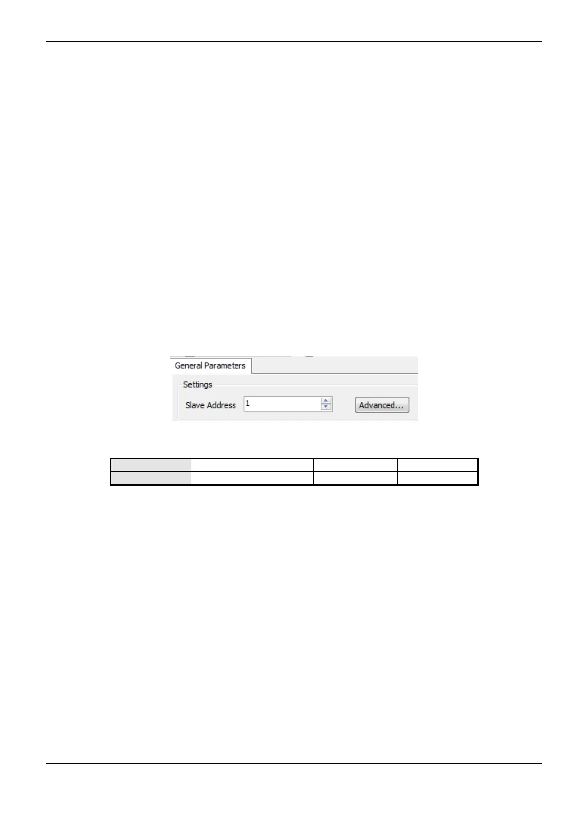
The general parameters, found on the MODBUS protocol initial screen (Figure 4-22), are defined as:
Figure 4-22. MODBUS RTU Slave Configuration Screen
Table 4-56. Slave Configurations
The MODBUS slave protocol communication times, found in the “Advanced…” button on the
configuration screen, are divided in: Task Cycle, Send Delay and Minimum Interframe, as shown in
Figure 4-23 and in Table 4-57.
 Loading...