4. Configuration
97
Mappings Configuration – Configuration via Direct Representation (%Q)
The settings of the MODBUS relations, viewed in Figure 4-26 and Figure 4-27, follow the
parameters described in Table 4-62:
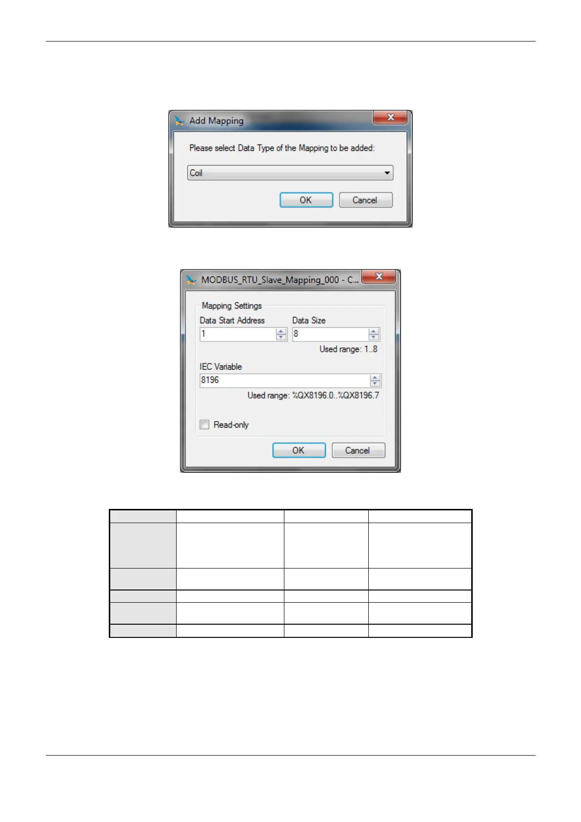
Figure 4-26. Adding MODBUS Relations
Figure 4-27. Configuring the MODBUS Relation
Coil (1-bit)
Holding Register (16-bit)
Input Status (1-bit)
Input Register (16-bit)
Initial address of the
MODBUS data
Initial address of variables
(%Q)
Table 4-62. Slave Mappings
Notes:
Options: the values written in the column Options may vary according with the configured
MODBUS data.
 Loading...