4. Configuration
114
TCP Port: if there are multiple instances of the protocol added in a single Ethernet interface,
different TCP ports must be selected for each instance. Some TCP ports, among the possibilities
mentioned above, are reserved and therefore cannot be used. They are: 80, 8080, 1217, 1740, 1741,
1742,1743 and 11740.
The settings present on the "Filters ..." button, described in Table 4-79, are relative to the TCP
communication filters:
Specifies a range of IPs with write
access in the variables declared in
the MODBUS interface
0.0.0.0 to
255.255.255.255
Specifies the subnet mask in
conjunction with the parameter IP
filter for writing
0.0.0.0 to
255.255.255.255
Specifies a range of IPs with read
access in the variables declared in
the MODBUS interface
0.0.0.0 to
255.255.255.255
Specifies the subnet mask in
conjunction with the IP filter
parameter for reading
0.0.0.0 to
255.255.255.255
Table 4-79. IP Filters
Note:
Filters: filters are used to establish a range of IP addresses that have write or read access to
MODBUS relations, being individually configured. The permission criteria is accomplished through
a logical AND operation between the Write Mask Filter and the IP address of the client. If the result
is the same as the IP Filter for Writing, the client is entitled to write. For example, if the IP Filter for
Writing = 192.168.15.0 and the Mask Filter for Writing = 255.255.255.0, then only customers with
IP address = 192.168.15. x shall be entitled. The same procedure is applied in the Read Filter
parameters to define the read rights.
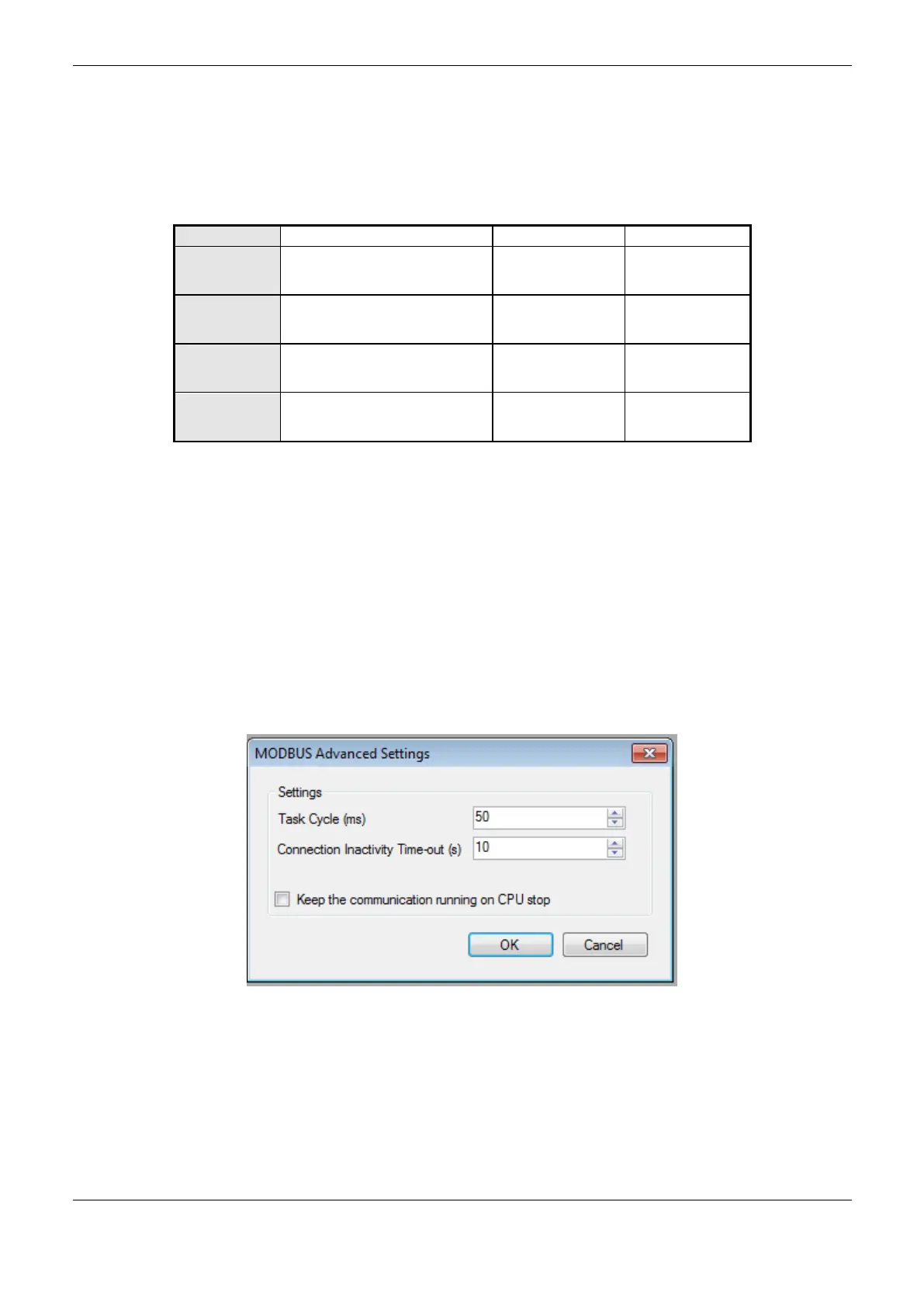
The communication times of the MODBUS server protocol, found on the "Advanced ..." button of
the configuration screen, are divided into: Task Cycle and Connection Downtime Time-out.
Figure 4-38. MODBUS Server Advanced Settings Configuration Screen
 Loading...