2. Technical Description
7
CPU’s Informative and Configuration Menu. For further information regarding the MS switch, see
Configuration - Memory Card.
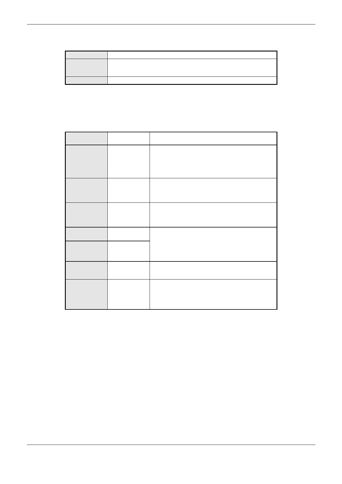
Switch placed on the module upper part. Used for diagnostics visualization on
the graphic display or for navigation through the informative menu and CPU
configuration.
Switch placed on the frontal panel. Used to securely remove the memory card.
Table 2-2. Keys Description
On the frontal panel the connection interfaces of Nexto Series CPUs are available. These interfaces
are: Ethernet communication, serial communication and memory card interface. Table 2-3 presents a
brief description of these interfaces.
NX3004
NX3005
NX3010
NX3020
NX3030
RJ45 communication connector standard 10/100Base-TX.
Allows the point to point or network communication.
For further utilization information, see Ethernet Interfaces
Configuration section.
RJ45 communication connector pattern 10/100Base-TX.
Allows the point to point or network.
For further utilization information, see Ethernet Interfaces
Configuration section.
DB9 female connector for RS-232 pattern communication.
Allows the point to point or network.
For further utilization information, see Serial Interfaces
Configuration section.
DB9 female connector for RS-485 and RS-422 standard.
Allows point-to-point or network communication.
For further utilization information, see Serial Interfaces
Configuration section.
6-terminal connector with fixing. It powers Nexto series
modules connected at the same bus, providing 15 W of
power.
Memory card slot. Allows the use of a memory card for
different types of data storage such as: user logs, Web
pages, project documentation and files.
For further utilization information, see Configuration-Memory
Card section.
Table 2-3. Connection Interfaces
 Loading...