4. Configuration
170
Listened port address to client
connection. Used when the client
connection isn’t through IP.
Connected client IP, used when the
client connection is through IP.
1.0.0.1 to 223.255.255.254
IEC 60870-5-104 address, if the
connected client is through IP.
Time period (in seconds) that the
device waits the receiving of an
acknowledge message after sent an
APDU message type I or U (data),
before close the connection.
Time period (in seconds) that the
device waits to send a watch
message (S-Frame) acknowledging
the data frame receiving.
Time period (in seconds) in what is
going to be sent a message to link
test in case there is no transmission
by both sides.
Maximum number of data messages
(I-Frame) transmited and not
acknowledged.
Maximum number of data messages
(I-Frame) received and not
acknowledged.
Table 4-105. Server IEC 60870-5-104 Link Layer Configuration
Note:
Time-out: The fields “Time-out t1(s)”, “Time-out t2(s)” and “Time-out t3(s)” are dependants
between themselves and must be configured in a way that “Time-out t1(s)” be bigger than “Time-out
t2(s)”, and “Time-out t3(s)” be bigger than “Time-out t1(s)”. If any of these rules be not respected,
error messages are going to be generated during the project compilation.
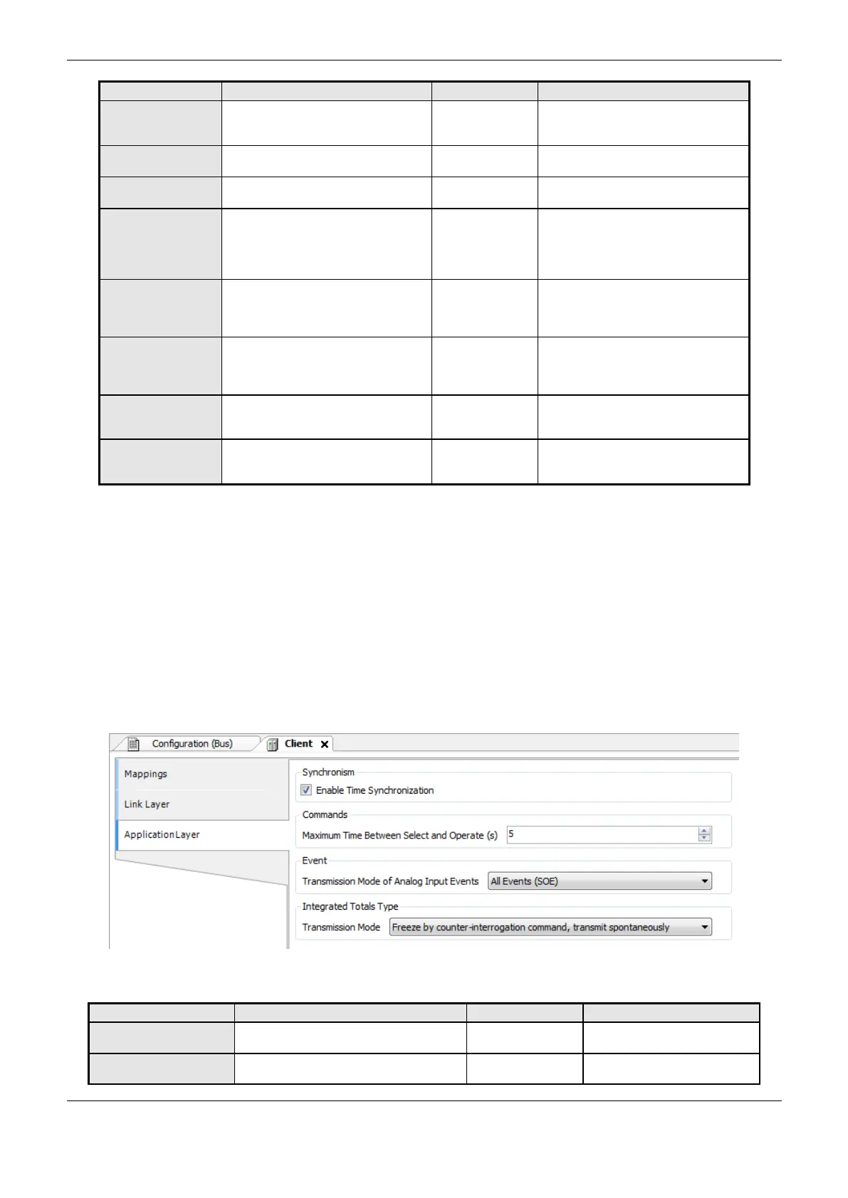
Application Layer
To configure the Server IEC 60870-5-104 application layer, shown on Figure 4-79, follow the
parameters described on Table 4-106.
Figure 4-79. Server IEC 60870-5-104 Application Layer Configuration Screen
Enable Time
Synchronization
Option to Enable/Disable time sync
request
Maximum Time
Between Select and
Time period in which the selection
command will remain active ( the count
 Loading...