7. Maintenance
348
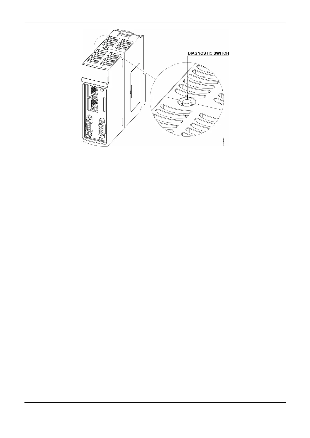
Figure 7-1. Diagnostic Switch
With only a short touch, the CPU starts to show the bus diagnostics (when active, otherwise shows
the “NO DIAG” message). Initially, the Tag is visualized (configured in the module properties in the
MasterTool IEC XE software, following the IEC 61131-3 standard), in other words, the name
attributed to the CPU, and after that all diagnostics are shown, through CPU display messages. This
process is executed twice on the display. Everything occurs automatically as the user only has to
execute the first short touch and the CPU is responsible to show the diagnostics. The diagnostics of
other modules present on the bus are also shown on the CPU graphic display by a short press in the
diagnostic module button, in the same presentation model of diagnostics.
Figure 7-2 shows the process starting with the short touch, with the conditions and the CPU times
presented in smaller rectangles. It is important to stress the diagnostics may have more than one
screen, in other words, the specified time in the block diagram below is valid for one of them.
 Loading...