MM-400A
8. Operation Screens
8-63
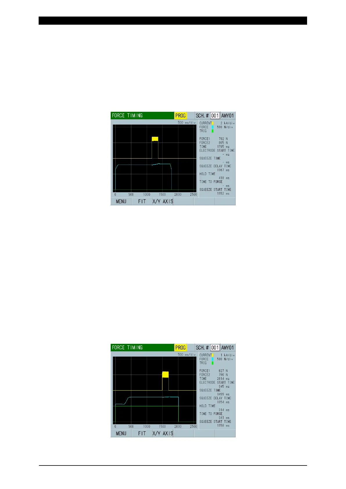
• Way to start when the weld force reaches the preset TRIGGER LEVEL
The timing from when the force starts, the current flows, until when the force ends is
measured. When the weld force exceeds TRIGGER LEVEL, the measurement
starts. For the force trigger level, refer to “m-5. EXTEND SETUP (5) Screen.”
Taking the force start point as the reference point of time axis (horizontal axis),
force and current waveforms are displayed and each timing can be observed. The
unit of horizontal axis is ms. Force 1, Force 2, Force time, Current stabilization time,
Hold time, and Current start time are displayed in the area of displaying measured
values.
• Way to start measurement using the external input signal “FORCE
TRIGGER” (force valve driving signal) together
The timing from when the force valve driving signal of Head is input, the Head starts
applying force, the welding current flows, the force valve driving signal is turned off,
until when the force ends is measured.
Turn off 24 V DC by inputting the external input signal “FORCE TRIGGER”
simultaneously with the force valve driving signal of Head. When the force valve
uses the Head with 24 V DC specification, you can divide the force valve driving
signal to input. The input terminal of the external input signal “FORCE TRIGGER”
does not have polarity.
Taking the timing of the external input signal “FORCE TRIGGER” input as the
reference point of time axis (horizontal axis), force external trigger, force and
current waveforms are displayed on the screen and each timing can be observed.
The unit of horizontal axis is ms. Since the screen is for measuring the timing, the
vertical axis has no unit. Force 1, Force 2, Force time, Force start time, Squeeze
time, Force stabilization time, Hold time, Force completion time, and Current start
time are displayed in the area of displaying measured values.