MM-400A
12. Data Communication
12-2
(2) Configuration
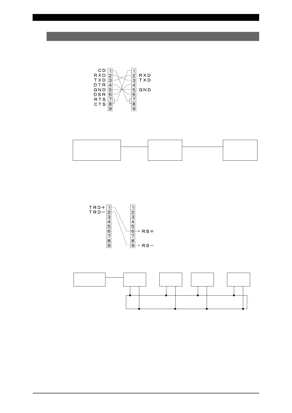
a. RS-232C
U
S
B
MM-400A
Host computer USB-RS232C
conversion
adapter
cable
communication
RS-232C
* Prepare the USB-RS232C conversion adapter at customer’s side.
* The RS-232C communication cable is optional.
b. RS-485
U
SB
MM-400A
MM-400A
TRD+ TRD- RS-RS+ RS-RS+
100Ω
MM-400A
RS-RS+
100Ω
Host computer
Device No.: 1 Device No.: 2 Device No.: n
USB-RS485
conversion
adapter
* Prepare the USB-RS232C conversion adapter and cable at customer’s side. The
above diagram is an example. The connector on the host computer side changes
according to the conversion adapter.
* Mount 100 Ω of termination resistance at either end of the RS-485 cable.
* The RS-485 connector (with termination resistance) is optional.
* Up to 31 devices can be connected.
* In the single-directional communication, only one device can be connected.
Pin No.
Female
Pin No.
Male
Pin No.
Female
Pin No.
Male