MM-400A
10. Interface
10-3
(2) Description of the External I/O Signals
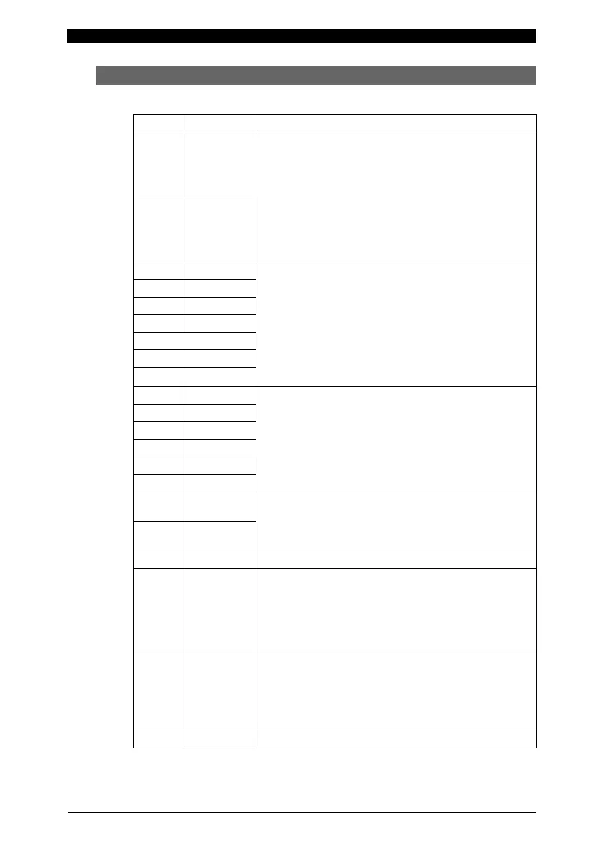
a. Input Connector (D-Sub, 25-pin, female)
Pin No. Name Function
1 INT.24 Pins 1 and 2 are INT.24V and EXT.COM pins.
Connect them as follows depending on the usage:
When using contacts or open-collector (sink-type) PLC
(Programmable Logic Controller) as input signals to the I/O
connectors, connect pins 1 and 2.
When using a voltage-output (source type) PLC as input
signals to the I/O connectors, connect pin 2 to the COM
terminal of the PLC.
Refer to “(3) Connection of Input Signals.”
2 EXT.COM
3 SCH1 Select the schedule No. by the binary combination of closed
pin numbers among pins 3 to 9.
The schedule No. selected by the I/O connectors has
precedence over that selected on screen. If you wish to
select the schedule No. through on-screen manipulation,
leave all pins 3 to 9 open.
For timing, refer to Chapter 11, “(1) Schedule Number
Selection.” You cannot change schedule No. during
measurement operation.
4 SCH2
5 SCH4
6 SCH8
7 SCH16
8 SCH32
9 SCH64
10 IN1 User input terminals.
Refer to Chapter 8, “o-1. EXT INPUT/OUTPUT (1) Screen”
for function and setting.
14 IN2
15 IN3
16 IN4
17 IN5
18 IN6
19 IN7 User input trigger terminals. Refer to Chapter 8, “o-1. EXT
INPUT/OUTPUT (1) Screen” for function and setting.
(Trigger detection by IN8 input can also be performed with
pins 22 and 24.)
20 IN8
11, 21 COM COM terminal for input signals.
12 NO CURR Input terminal for the NO CURR signal.
Be sure that it closes at least the flow of welding current and
opens after the flow of welding current.
If no welding current flows while this pin is closed, a
lack-of-current error occurs when the pin opens.
For timing, refer to Chapter 11, “(2) No CURR Operation.”
13, 25 NO CURR
_AC/DC24V
These pins are used to detect lack of current using voltage.
Input 24 V AC or DC voltage at least 10 ms prior to the flow
of welding current, and stop the input after the current flow.
If no welding current flows while this terminal is supplied
with voltage, a lack of current error is displayed when the
voltage input stops.
23 - Unused.