MM-400A
10. Interface
10-5
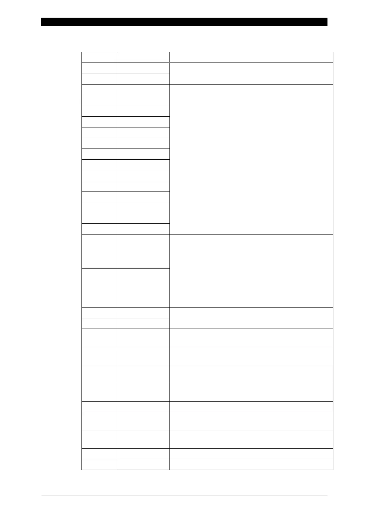
b. Output Connector (D-Sub, 37-pin, female)
Pin No. Name Function
1 OUT COM COM terminal for outputs.
9 OUT COM
2 OUT1 Contact output terminals. (Semiconductor relay.
Capacity: 24 V AC/DC, 20 mA)
The contacts close according to the function.
Refer to Chapter 8, “o-2. EXT. INPUT/OUTPUT Screen
(2) (3) Screen” for function and setting.
3 OUT2
4 OUT3
5 OUT4
6 OUT5
7 OUT6
8 OUT7
10 OUT8
11 OUT9
12 OUT10
13 OUT11
14 OUT12
17 COM COM terminal for pins 18 and 36 for 24 V DC input and
pins 19 and 37 for INT.24V.
35 COM
18 DC IN +24V Can be used without inputting 90 to 250 V AC by
inputting 24 V DC from external device.
When using with the 24 V DC power supply, be sure to
make connections of pins 18 and 36 to 24 V DC and pins
17 and 35 to 0 V.
(Note) When inputting 24 V DC, do not connect input
power supply to the power cable connector. When
connected at the same time, they are short-circuited and
it results in malfunction
36 DC IN +24V
19 INT.24V Connected to INT.24V of input connector.
37 INT.24V
20 CURR SIG Analog current signal terminal (approx. 2 V/range max.
value)
21 VOLT SIG Analog voltage signal terminal (approx. 2 V/range max.
value)
22 CURR TRG SIG Analog current trigger signal terminal (3.3 V)
Goes to approx. 3.3 V if a current flows.
23 VOLT TRG SIG Analog voltage trigger signal terminal (3.3 V)
Goes to approx. 3.3 V if a voltage occurs.
24 SIG GND COM terminal for analog signals.
25 FORCE SIG Analog force signal terminal. Approx. 5 V/sensor rating
max. (at 1 mV/V rating)
26 DIST SIG Analog displacement signal terminal. (Note) Refer to
“About the analog displacement signal.”
27 SIG GND COM terminal for analog signals.
28 to 34 - Unused.