MM-400A
8. Operation Screens
8-84
m. EXTEND SETUP Screen
This screen is displayed only in the force/displacement-equipped specification.
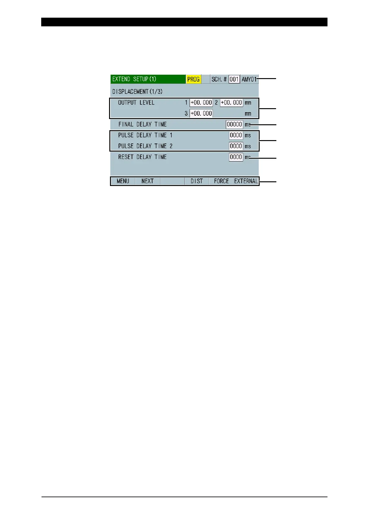
m-1. EXTEND SETUP (1) Screen: DISPLACEMENT (1/3)
(1) SCH.#
Shows the measurement schedule number used (1 to 127). On the other hand,
you can change schedules by selecting this field and inputting a value.
(2) Schedule name
Shows the name of SCH.#. This can be set in the BASIC SETUP (1) screen.
(3) OUTPUT LEVEL
If the measured value reaches the set displacement levels, you can output
signals from external outputs DIST LEV1, DIST LEV2, and DIST LEV3. There
are three input fields because you can specify three levels for a single
measurement and measure the displacement level at three locations. The
setting range varies depending on the SENSOR STEP setting in the EXTEND
SETUP (3) screen: DISPLACEMENT (3/3).
• When a sensor with 1 µm resolution or less is used: -30.000 mm to +30.000
mm
• When a sensor with 1.1 µm resolution or more is used: -300.00 mm to
+300.00 mm
(4) FINAL DELAY TIME
Set a delay time (welding/displacement stabilization time) from the end of
current flow or from when the external displacement trigger turns OFF to when
the displacement measurement position is reached in the range from 00000 to
10,000 ms. Be sure that the total of the current flow time, the displacement
delay time (including the cooling time between current flows), cooling time, and
time to judge the current flow end does not exceed the maximum current
measurement range. Make a measurement in a marginal range since the time
to judge the current flow end changed depending on the magnitude of the
current.
When displacement trigger is not used:
If, following the end of the first step current flow, the second step current flow
occurs before the displacement delay time elapses, the instrument measures
the displacement delay time again after the end of the second step current
flow.
The instrument measures the displacement after the displacement delay time
elapses following the end of current flow.