73
Rammax 1515-M/-MC/-MI/-MCI
Index: a; Issued 08/2010
Only use a transport vehicle that has sufcient load bearing
capability to transport the machine. Check the load distributi-
on on the transport vehicle.
Lifting the machine onto the transport vehicle
Only use lifting equipment with a load lifting capability of at
least 2,000 Kg.
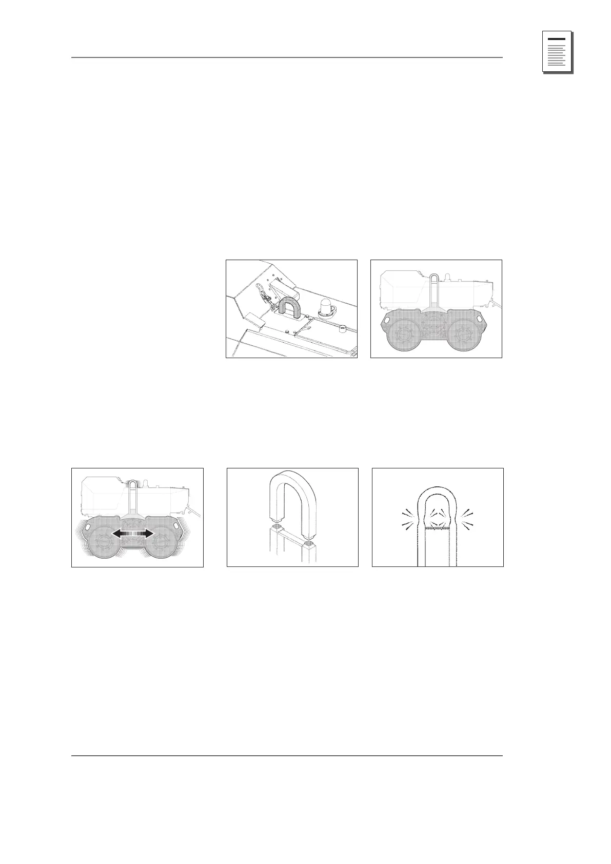
The machine has a transport hoop (Abb MT1). It is attached to
the casing (Fig. MT2). This ensures that the rubber-bonded me-
tal, between the upper and lower casing, is not stressed when
the machine is hoisted. Only the transport hoop is to be used
to lift the machine.
Fig. MT2: Upper and lower casing
Fig. MT1: Transport hoop
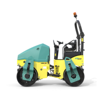
The transport hoop must always swing free when the machine
is being used (Fig. MT3). Lifting equipment attached to the trans-
port hoop will permanently rub against the transport hoop due
to the casing's swinging movement. The material will be worn
away and the transport hoop's cross-section will be reduced.
This will reduce its load bearing capability (Figs. MT3 to MT5).
Fig. MT4: Cross-sectionFig. MT3: Swinging movement Fig. MT5: Cross-section
The area underneath the transport bracket is protected against
the ingress of foreign matter and dirt by a foam sheet. Lifting
gear attached to the machine can damage the foam sheet.
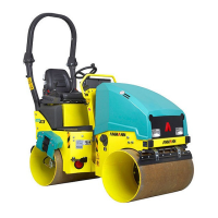
It is possible that the lifting equipment (chains, ropes) might
become trapped inbetween the transport hoop and the casing
(Fig MT6). If the hoop can no longer swing freely together with
the chassis due to the trapped lifting gear then this will result
in material fatigue at the weld seam (Fig. MT7) and strain the
components. This can lead to cracking of the transport hoop
and in the central beam of the chassis around the yweight
housing (Fig. MT8).
transporting the Machine