Chapter 2 Preparation
2-8
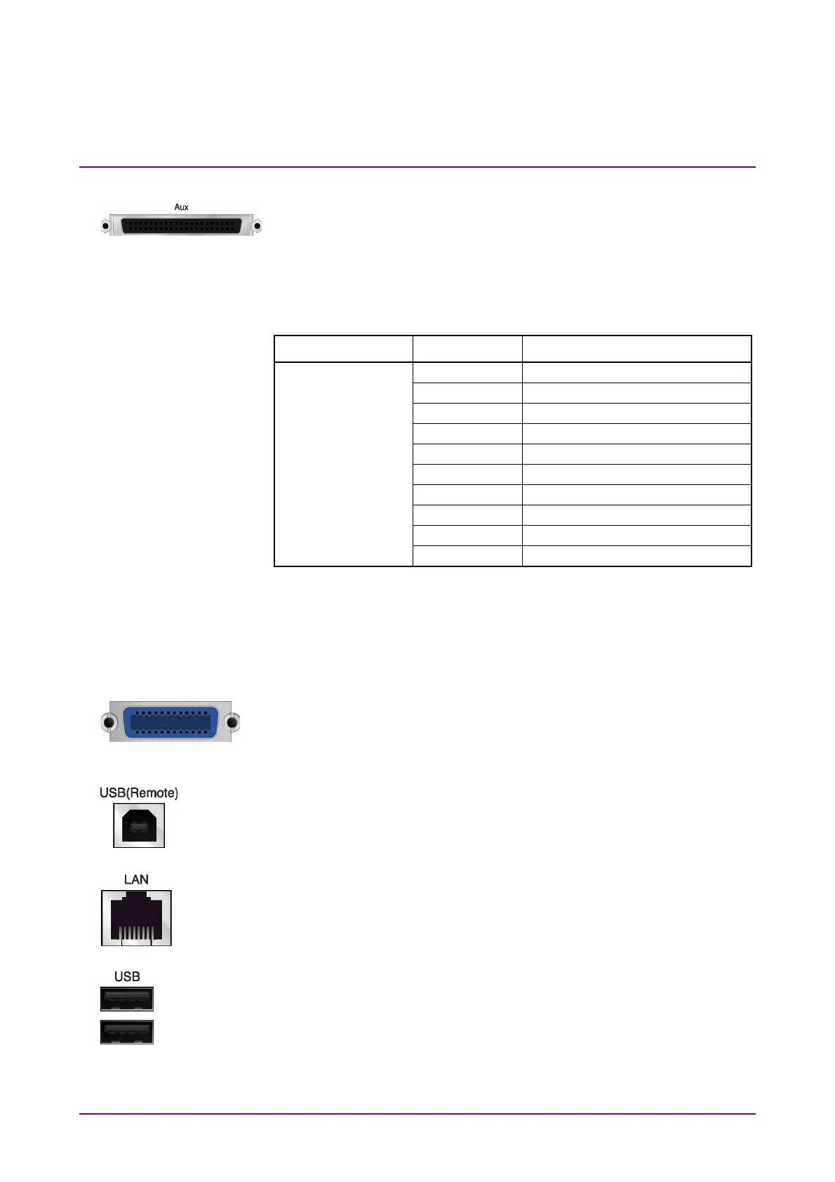
6 AUX connector
This is a complex connector for inputting an error rate measurement
signal and inputting a baseband clock reference signal of the Vector
Signal Generator (optional). See Table 2.1.2-1, for the internal pin
assignment of the AUX connector.
Table 2.1.2-1 AUX connector
Function Pin Number Signal Name
SG
13 MARKER1
11 GND
38 MARKER2
36 GND
39 MARKER3
16 GND
42 PULS_MOD
41 GND
22 BB_REF_CLK
20 GND
Do not connect anything to connectors not listed in Table 2.1.2-1, because
they are interface connectors provided for device maintenance.
7 GPIB connector
For external control via GPIB
8 USB connector (type B)
For external control via USB
9 Ethernet connector
Connects PC or Ethernet network.
10 USB connector (type A)
Used to connect a USB keyboard or mouse or the USB memory supplied.
GP-IB