2-11 Test Panel Connectors Quick Start Guide
2-20 PN: 10580-00305 Rev. L MS20xxC UG
2-11 Test Panel Connectors
The connectors and indicators that are located on the test panel of the VNA Master are shown
and described in the following sections.
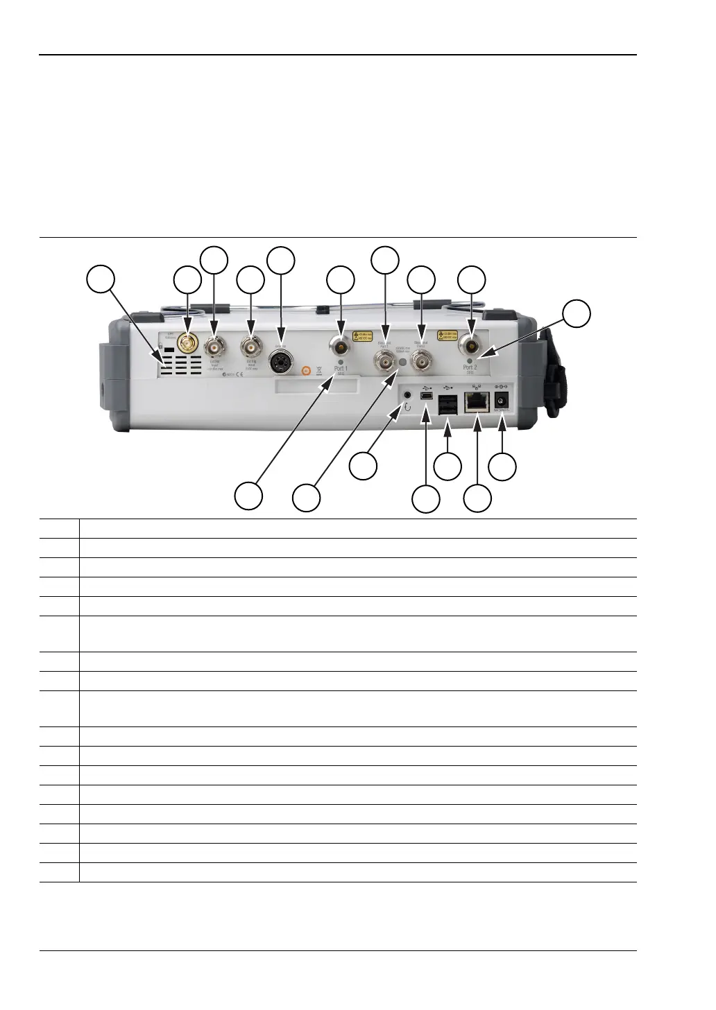
MS202xC Test Panel Connectors
The connectors and indicators that are located on the test panel of the MS2026C, MS2027C,
and MS2028C are shown in Figure 2-13 and are described in the table below the figure.
1 Fan Exhaust Port
2 GPS Antenna Input for Option 31
3 External Reference Input
4 External Trigger Input
5 RF Detector Interface (for Option 5)
6 Test Port 1 (50 ohm)
The corresponding LED turns green when the port is transmitting.
7 Bias Input Port 1
8 Bias Input Port 2
9 Test Port 2 (50 ohm)
The corresponding LED turns green when the port is transmitting.
10 Port 2 LED
11 External Power Input
12 LAN Connection
13 USB Interface, Type A (2 connectors, Full Speed USB 2.0)
14 USB Interface, Type Mini-B (Full Speed USB 2.0)
15 Headset Jack
16 Bias Status LED
17 Port 1 LED
Figure 2-13. MS202xC Test Panel Connectors
1
2
3
4
5
6
7
8 9
10
15
16
11
12
13
14
17