2-11 Test Panel Connectors Quick Start Guide
2-22 PN: 10580-00305 Rev. L MS20xxC UG
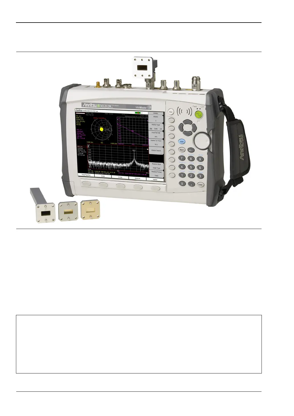
In Figure 2-15, a waveguide-coax adapter at Test Port 1 provides test connections, and typical
waveguide calibration components are shown below the VNA Master.
LAN Connection
The RJ45 connector is used to connect the VNA Master to a local area network. Refer to
Figure 2-13, item “12” on page 2-20. Integrated into this connector are two LEDs. The amber
LED indicates the speed of the LAN connection (ON for 10 Mb/s and OFF for 100 Mb/s), and
the green LED flashes to show that LAN traffic is present. The instrument Ethernet address
can be set automatically using DHCP, or manually by entering the desired IP address,
gateway address, and subnet mask. These settings are described in more detail in
Appendix G, “More About DHCP”.
Figure 2-15. Waveguide-Coax Adaptor and Waveguide Calibration Components
Note
An active Ethernet cable must be connected to the MS20xxC before it is turned
ON in order to enable the Ethernet port for DHCP or for a static IP address.
Depending upon local conditions, the port may remain enabled when changing
from DHCP to static IP address, when changing from static IP address to DHCP,
or when temporarily disconnecting the Ethernet cable.
If the port becomes disabled, then ensure that an active Ethernet cable is attached
to the MS20xxC before cycling the power OFF and back ON.