Operational Control Panel (OCP)
31
Antelope Camera Systems
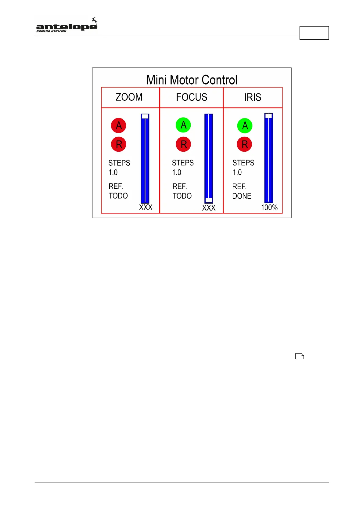
If you have mini motors attached to the lens:
- A red A indicates an deactivated and a green A an activated motor.
- A green R indicates a motor being in reverse mode.
- Steps allows to fine tune the step size of the motor.
Values range from 0.1-3.0
By turning the Select dial (Q) you can scroll and select between Reference, Steps, R and A
settings for all motors. The arrow indicates the chosen item. Press the Select dial (Q) to change
the respective item.
Note! If Reference (REF.) indicates TODO, you have to calibrate the respective motor : This is
done by Selecting REF. with the Select Dial (Q). Then start the calibration by pressing the Select
Dial (Q). After the calibration is finished correctly, the display switches from TODO to Done.
51