Remote Control Panel (RCP)
67
Antelope Camera Systems
5.5 RCP Display
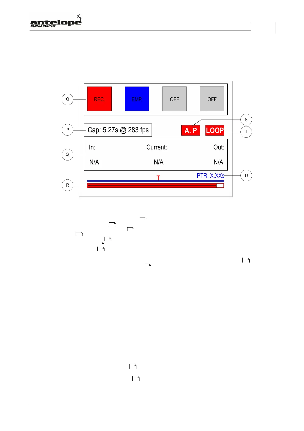
The RCP Display (N)
O. Squares representing the 4 memory banks
P. Memory capacity indicator
Q. Sequence In and Out Point indicator
R. Timleline
S. Autoplay Mode indicator
T. Loop Mode indicator
U. Pre-Trigger indicator
In the top line of display four squares representing the four video memory banks (O) are
shown. These squares change their color depending on the state in which they are.
5.5.1 Memory Capacity Indicator
The memory capacity indicator (P) displays the maximal recording time in seconds at the chosen
frame rate.
5.5.2 Loop Mode Indicator
The Loop Mode Indicator (T) displays the loop mode status.
If the Loop Mode Indicator (T) is displayed with a transparent background it indicates that Loop
Mode is switched off.
If the Loop Mode Indicator (T) is displayed with a red background it indicates that Loop Mode is
switched on.
5.5.3 Autoplay Mode Indicator
The Autoplay Mode Indicator (S) displays the loop mode status.
If the Autoplay Mode Indicator (S) is displayed with a transparent background it indicates that
Loop Mode is switched off.
78
67
68
68
67
67
76
78
78
72
72