Artec Leo
1. After Leo warms up to its optimal temperature, the scanning screen opens
up.
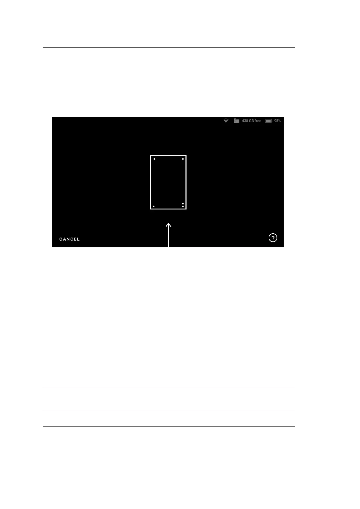
2. If there is no Calibration board in the eld of view, Leo displays the screen as
shown in Figure ??. In this case, simply point Leo to the Calibration board
to open the scanning screen.
Figure 39: Leo’s screen when there is no Calibration board in its eld of view.
3. Hold Leo within the distance range of 66.5 cm - 106.5 cm from the calibration
board, throughout the scanning procedure.
4. Point Leo to the Calibration board and start scanning (See Figure ??). There
are multiple trajectories you should cover with your scanner, to perform
recalibration.
4. The green dot in represents the center of the Calibration board, and the green
circle represents the Calibration board, i.e. your eld of view (See Figure ??).
5. The arcs represent the respective trajectories you will have to follow during
scanning.
6. To capture data, rst align the green dot with the intersection of the arcs.
Important: Make sure the green dot stays inside the green circle (eld of view)
during scanning. A red dot indicates that the scanner is out of the eld of view.
5.1. Leo Recalibration 69