AS64 series AC servo drive Control modes
-43-
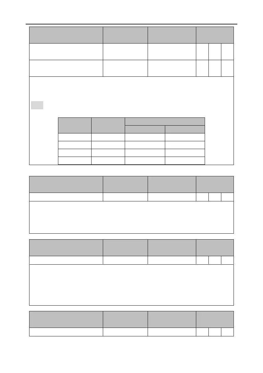
Numerator selection 1 for
electronic gear ratio
Numerator selection 2 for
electronic gear ratio
This group of signal is used to switch between a maximum of four electronic gear ratios.
Before using this function group, set P0.22 [Pulses per motor resolution] to 0 and then set
numerators (P0.25–P0.29).
Note: If the electronic gear ratio is switched through digital input, P4.10 [Upper computer type]
must be 0.
In PTP control mode, it works with the position commands 1–4 to trigger target position switching.
It is valid in the rising edge.
During the use, the target position is selected through the internal position commands 1–4, and
then the rising edge of this digital input triggers the switching.
Vibration control switching input
Signal of controlling the switching between the first vibration control frequency and second
vibration control frequency.
If this digital input is valid, the internal software uses P1.38 [Vibration control frequency 2] and
associated parameters. If it is invalid, the internal software uses P1.36 [Vibration control frequency
1] and associated parameters.
 Loading...