IP500/IP500 V2 Installation Page 235
15-601042 Issue 25i (03 January 2013)IP Office 8.0
System Components: IP500 Expansion Modules
IPO 500 Digital Station A Connections
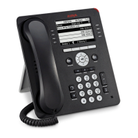
LEDs 1 to 16 or 1 to 30 indicate when a phone is connected. They do not indicate phone activity. The center LED indicate
the module status (Green = Okay, Red = Error, Flashing = Loading firmware).
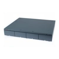
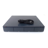
DC power input port. Used for connection of the power lead from an Avaya earthed 60W external
power supply unit supplied with the expansion module. A locale specific IEC60320 C13 power cord
for the external PSU is required but is not supplied with the module.
For IP Office Release 7.0, the modules support just phones requiring TCM ports .
9-Way D-Type socket. For Avaya use only.
RJ45 Socket. Used for direct connection to an Expansion port on an IP Office control unit using the
Expansion Interconnect cable supplied with the module.
Protective Ground point. Use of a protective ground is required for all installations, see Grounding
(Earthing) . Where the module is connected to analog extensions in another building, an IP Office
Phone Barrier Box V2 (101V) is required at both ends, see Lightning Protection/Out-of-Building
Connections .
All expansion modules are supplied with a base software level and should be upgraded to match the core software of the
control unit in the IP Office system.
IPO 500 Digital Station 16A RJ21 UNIT ASSY
IPO 500 Digital Station 30A RJ21 UNIT ASSY
IPO IP500 RACK MNTG KIT V2
Expansion modules include an external power supply unit (PSU) and an appropriate interconnect cable. They do not
include a locale specific power cord for the external PSU or any phone extension cables.
381
34
390 390
146
384
91
40
 Loading...