Camera Functional Description AW00089317000
48 Basler ace GigE
The pixel data leaves the image buffer and passes back through the FPGA to an Ethernet controller
where it is assembled into data packets. The packets are then transmitted via an Ethernet network
to a network adapter in the host PC. The Ethernet controller also handles transmission and receipt
of control data such as changes to the camera’s parameters.
The image buffer between the sensor and the Ethernet controller allows data to be read out of the
sensor at a rate that is independent of the data transmission rate between the camera and the host
computer. This ensures that the data transmission rate has no influence on image quality.
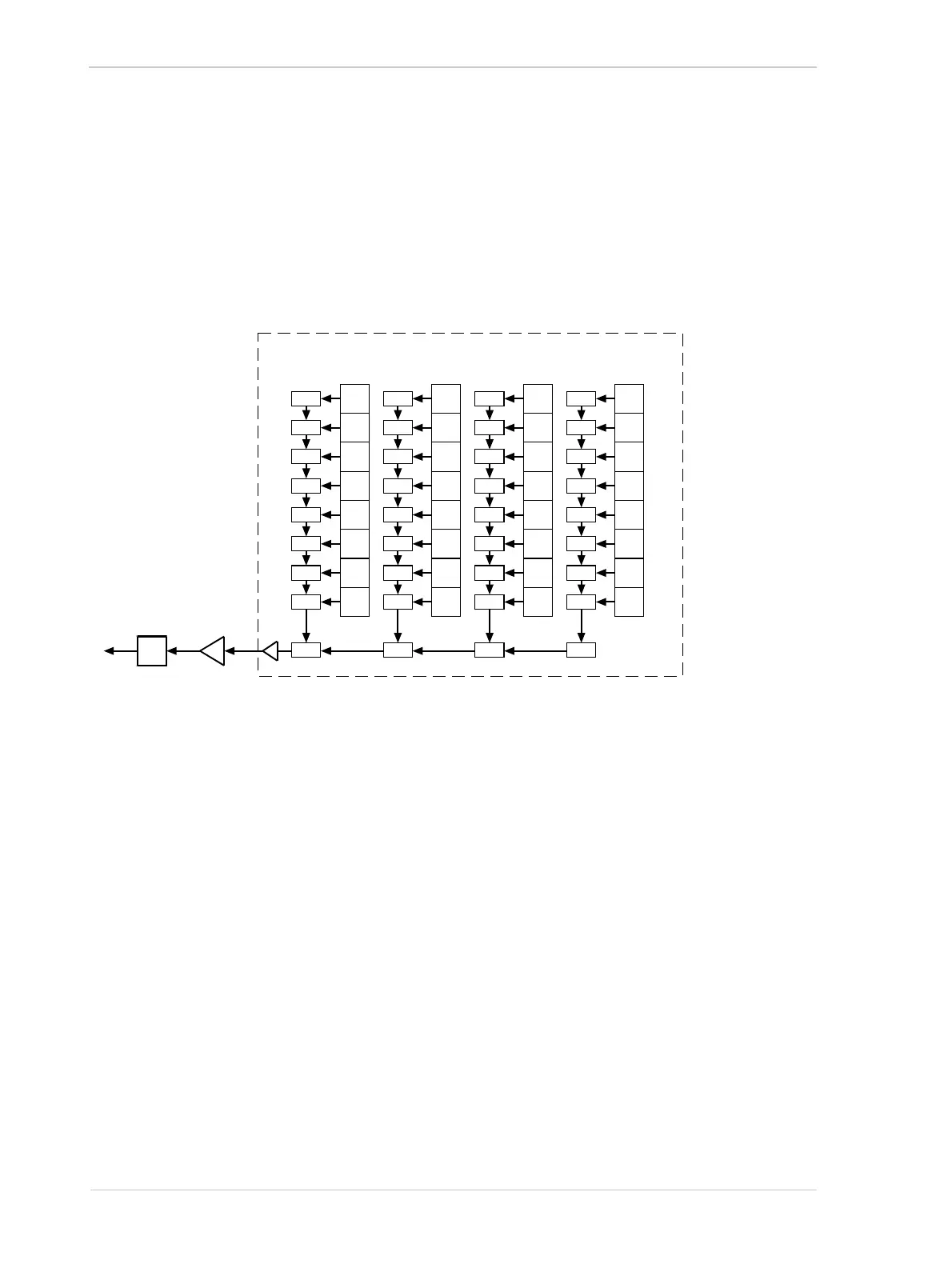
Progressive Scan CCD Sensor
Vert.
Shift
Reg.
Vert.
Shift
Reg.
Vert.
Shift
Reg.
Vert.
Shift
Reg.
Pixels Pixels Pixels Pixels
Horizontal
Shift Register
ADC VGC
Fig. 29: CCD Sensor Architecture - Progressive Scan Sensors

 Loading...


