Cube
®
Installation & Startup
1MANUL963 Belanger, Inc. * PO BOX 5470. * Northville, MI 48167-5470 * Ph (248) 349-7010 * Fax (248) 380-9681 10-1
Chapter 10 Undercarriage Option
Undercarriage Overview
The Undercarriage can be mounted in-ground or above ground. Follow the appropriate instructions
for the one that suits your location. See the images below.
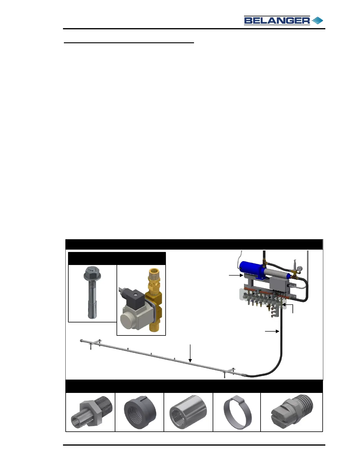
The Undercarriage will include the following parts that must be assembled in the field:
• (1) stainless steel water manifold with 3/4” NPT threads on each side
• (1) undercarriage water valve assembly. Assembled onto ICS prior to shipment.
• (3) 65° x 3.0 GPM nozzles
• (1) 3/4” stainless barb hose fitting
• (1) 3/4” stainless cap
• (1) 3/4” stainless steel coupling
• (2) 3/4” ear clamps for the water hose
• (4) lag bolts to mount Undercarriage to floor
Assembly Notes
• Before assembling any fittings onto the Undercarriage Manifold be sure the Manifold is
oriented properly. The nozzle openings in the Undercarriage Manifold are to be directed
toward the exit of the bay.
• Be sure to tighten the 3/4” stainless coupling and 3/4” barbed hose fitting to the side of the
manifold that also has the utility connections for an easy connection to the water line. Tighten
the 3/4” stainless cap to the opposite end.
• Apply liquid Teflon and Teflon tape to all stainless fittings before tightening.
 Loading...