Cube
®
Installation & Startup
18-8 Belanger, Inc. * PO BOX 5470. * Northville, MI 48167-5470 * Ph (248) 349-7010 * Fax (248) 380-9681 1MANUL963
Chapter 18 Pneumatic Connections
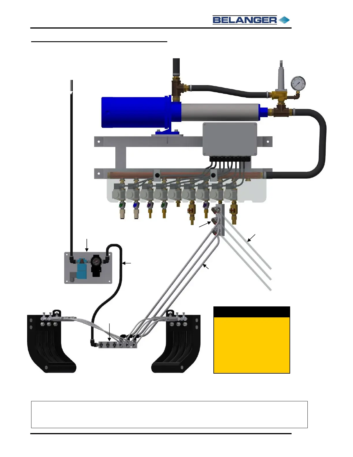
Triple Foam Chemical Solution Overview
Note: Chemical Solution is supplied to the right side of the Feed Block.
Note: The chemical solution lines from the top of the ports always go to the driver side Foam Pod and the
chemical solution lines from the bottom of the ports go to the passenger side Foam Pod.
If having difficulties drawing chemical
out to the wash bay, due to distance,
the 3/8” chemical lines from the ICS
Triple Foam injectors to the Utility
Manifold can be increased to 1/2"
lines. New fittings will be required for
the TF injectors and Utility Manifold
these are to be field supplied.