Cube
®
Installation & Startup
4-6 Belanger, Inc. * PO BOX 5470. * Northville, MI 48167-5470 * Ph (248) 349-7010 * Fax (248) 380-9681 1MANUL963
Chapter 4 Electrical Overview and Panels
Cube® Carriage Panel
DO NOT punch ANY holes in the top of the enclosure. It may allow
moisture to leak inside. Doing so voids all warranties.
NOTE TO ELECTRICIANS AND ARCHITECTS
The conduit schedule indicates that separation of 3 Phase and all other wires MUST be
strictly observed. Please read wiring notes within this chapter. Notes are also referenced
on sheet 11 of the Electrical Prints.
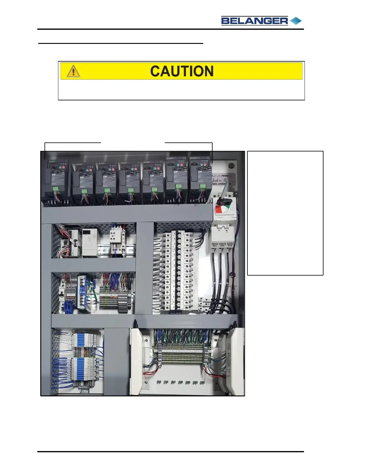
The above image shows the components located inside of the 208 VAC Cube® Carriage Panel Enclosure
REFER TO YOUR SUPPLIED ELECTRICAL PRINTS, AND
SITE-SPECIFIC DRAWINGS FOR INSTALLATION DETAILS


 To Next Page