EasyManua.ls Logo

Belanger CUBE - Page 253

Default Icon
288 pages
Print Icon
To Next Page IconTo Next Page
To Previous Page IconTo Previous Page
Loading...
Cube
®
Installation & Startup
1MANUL963 Belanger, Inc. * PO BOX 5470. * Northville, MI 48167-5470 * Ph (248) 349-7010 * Fax (248) 380-9681 19-17
Chapter 19 Initial Startup Procedure of Cube®
5) Inspect and Adjust the Carriage Assembly
5b) Check the Tension of the Shuttle Belt (cont.)
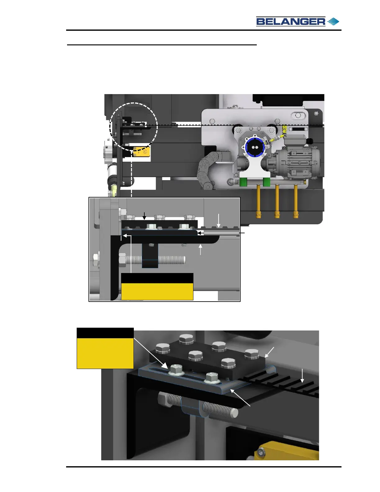
3) Mark a line on the Angle Mount to indicate the initial location of the Tension Plate before
loosening any fasteners. This will be used for reference.
4) Loosen the four (4) 1/4"-20 flanged hex head fasteners, just enough so that the Tension
Plate Weldment can slide, refer to the image below.
SW Shuttle
Timing Belt
Timing Belt
Clamp
Tension Plate Weldment
with 1/4"-20 flanged hex
head fasteners (2) per side
Step 4:
Loosen the four flanged
hex head fasteners (2 per
side) just enough so the
Tension Plate can slide.
Enlarged View of
Side Wheel Shuttle Belt
(Front View)
SW Shuttle
Timing Belt
Timing Belt
Clamp
Tension Plate Weldment
with (4) 1/4"-20 flanged hex head fasteners
Angle Mount
Step 3:
Mark a line on the Angle Bracket
at the end of the Tension Plate.

Table of Contents

Other manuals for Belanger CUBE