Cube
®
Installation & Startup
5-2 Belanger, Inc. * PO BOX 5470. * Northville, MI 48167-5470 * Ph (248) 349-7010 * Fax (248) 380-9681 1MANUL963
Chapter 5 Getting Started
Installation Overview
Width Considerations
Bay width is defined as the distance perpendicular to the centerline of the machine required for
the Cube® to operate without any obstructions. The spinning wheels should not be able to hit
conduits, cables, or any other equipment that may be mounted to the wall such as chemical
pumps, etc.
Note: The following width considerations will determine where the legs and rails will be clamped
onto the head beams.
OVERALL BAY CONSIDERATIONS
• Consideration should be given to any approach turns that a driver may encounter while
entering the bay that may be helped or hurt by the machine being offset.
• Door width such as a 10’ or 12’ wide door would ease vehicle loading more than an 8’
door, if the Cube® was placed off the door centerline.
• The Cube® Carriage Assembly is 13’-4” wide which is wider than the entrance door
opening. The forklift will have to angle the Carriage to enter the bay then straighten out
once past the door opening.
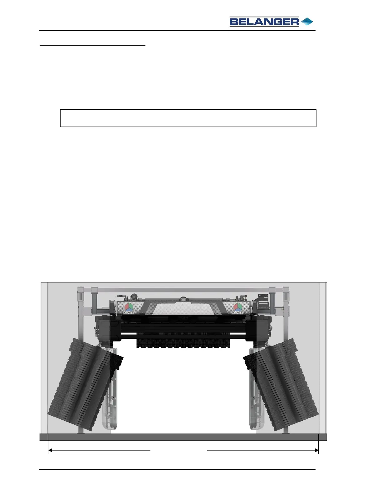
• The Bay width will determine the maximum angle that the Side Wheel Assemblies can
be tilted out when the Shuttle Assembly is in the furthest outward position. The image
below and on the following page will show the following:
➢ Ideal bay width 20’-4” and Side Wheels fully tilted outward, shown below.
➢ Ideal bay width 16’ and Side Wheels in vertical position, shown on following page.
➢ Minimum bay width 14’-9” will require the crossbeams to be shortened and the Leg
Assemblies to be moved inward, shown on following page.
Bay Width Considerations: Ideal Bay Width of 20’-4”