Cube
®
Installation & Startup
6-20 Belanger, Inc. * PO BOX 5470. * Northville, MI 48167-5470 * Ph (248) 349-7010 * Fax (248) 380-9681 1MANUL963
Chapter 6 Frame and Carriage Assembly
Frame Assembly: Position Frame in Bay
Place & Secure the Frame Assembly in Position
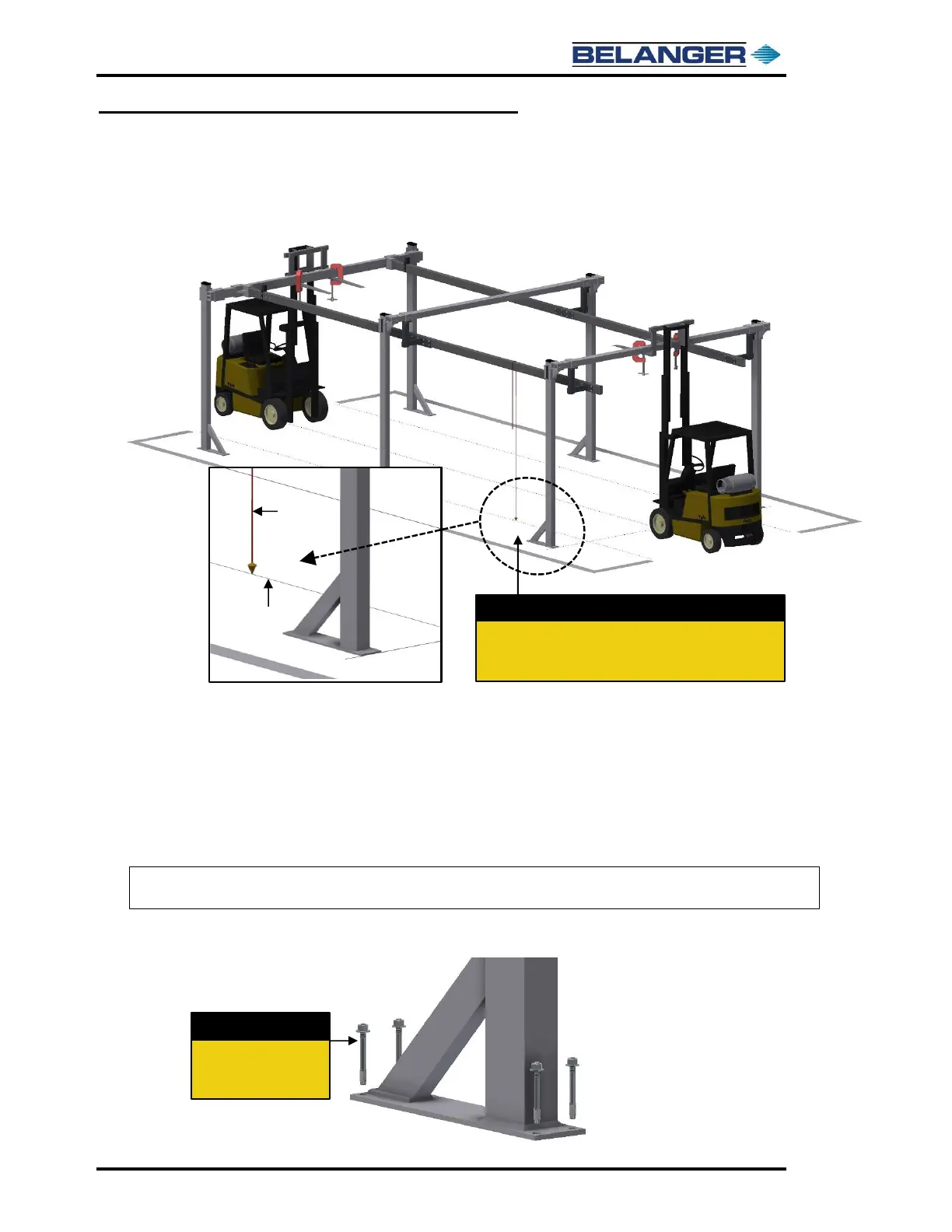
4) Use a plumb bob along the inside face of the driver side Rails to project the location of the
Rail to the ground and align it with the chalk line on the driver side of the bay.
5) Check the alignment of the driver side Rails with the chalk line in several spots so the Rails
will be parallel with the centerline between the doors.
6) Repeat Steps 4 and 5 for the for the passenger side Rails.
7) Once the Frame Assembly is positioned in the bay. Confirm the following criteria:
➢ Rails, Legs and Head Beams are level.
➢ Distance between the inside of the Rails is 125” for the entire length of the Rails.
➢ Distance from the ground to the underside of the Entrance and Exit Rails is 107”.
8) If no further adjustments are necessary, secure the six (6) Leg Assemblies to the floor
using the supplied 5/8” Lag Bolts in the Accessory Box.
9) Remove the nails and string that were used to mark the centerline of the bay.
Use a Plumb Bob to confirm the inside face of the Rails
aligns with the respective chalk line. Check several
locations on both the driver and passenger side of the bay.
Note: The Rails must be level and a minimum distance of 107” from the floor to the bottom of the
Rails. Rail spacing and leveling is CRITICAL for proper machine operation!
 Loading...