Performance Verication 97
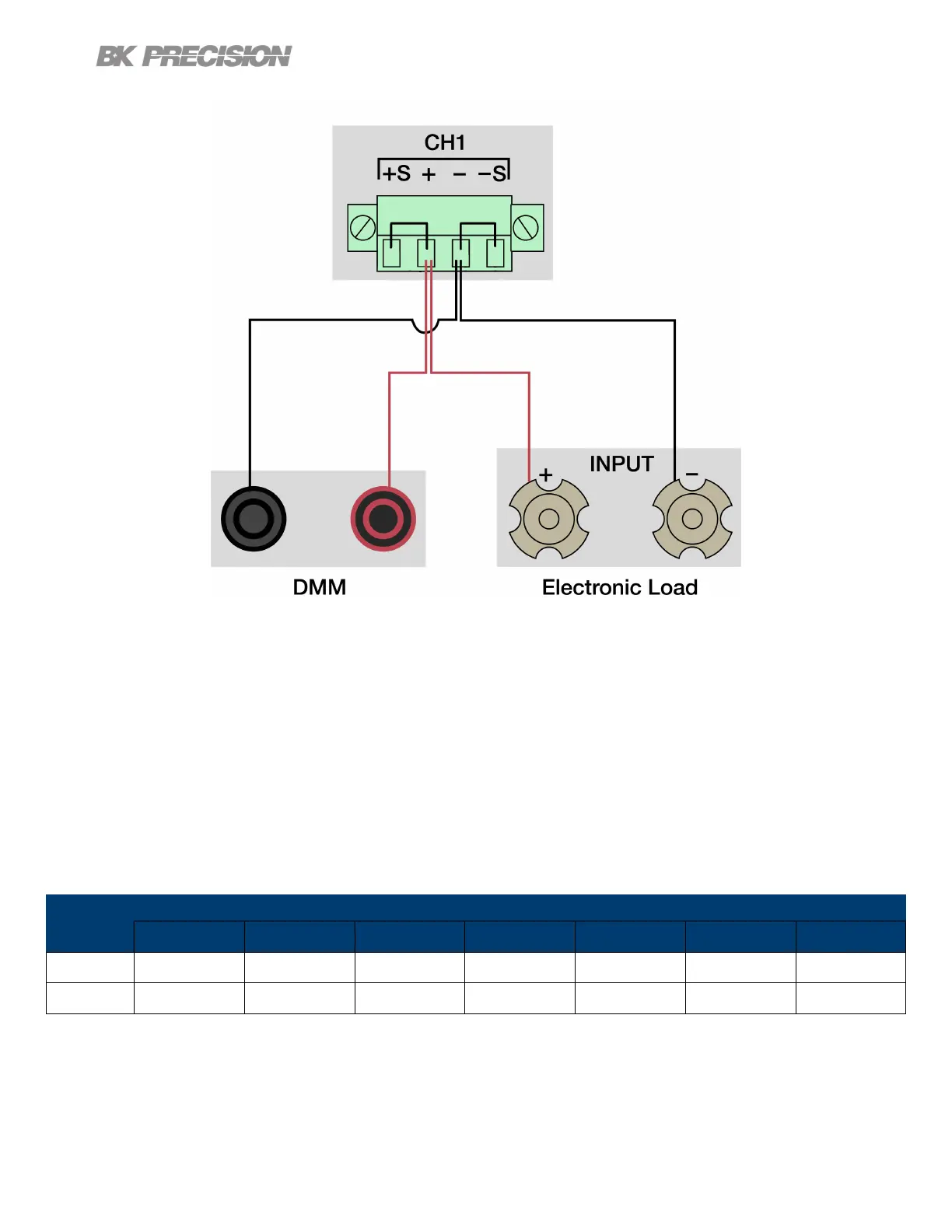
Figure 11.2 Rear Panel Wiring Diagram
8. Enable the electronic load. Monitor the power supply to ensure it remains in CV mode.If the power
supply switches to CC slightly lower the current on the electronic load until the power supply return
to CV mode.
9. Give the power supply some time to settle and record the DMM reading as V load.
10.Disable the electronic load and record the DMM reading as V noload.
11.Take the dierence between V load and V noload (V load - V noload) and record the value as the
voltage regulation. The dierence should be within the specication limit.
Model
Power Supply Settings Electronic
Load Settings
Load Regulation Limit
Voltage Current
Remote
Sense
Mode Current Lower Limit Upper Limit
9140 32.000 V 3.069 A Enabled CC 3.065 A - 6.2 mV + 6.2 mV
9141 60.000 V 1.666 A Enabled CC 1.650 A - 9 mV + 9 mV
Table 11.1
www.GlobalTestSupply.com
Find Quality Products Online at: sales@GlobalTestSupply.com
 Loading...