VC-6000
TM
Compact monitor Part C Binary-input block
- 16 - C100583.002 Components Vers. 07 © VC-6000
TM
Compact monitor Sept. 2011
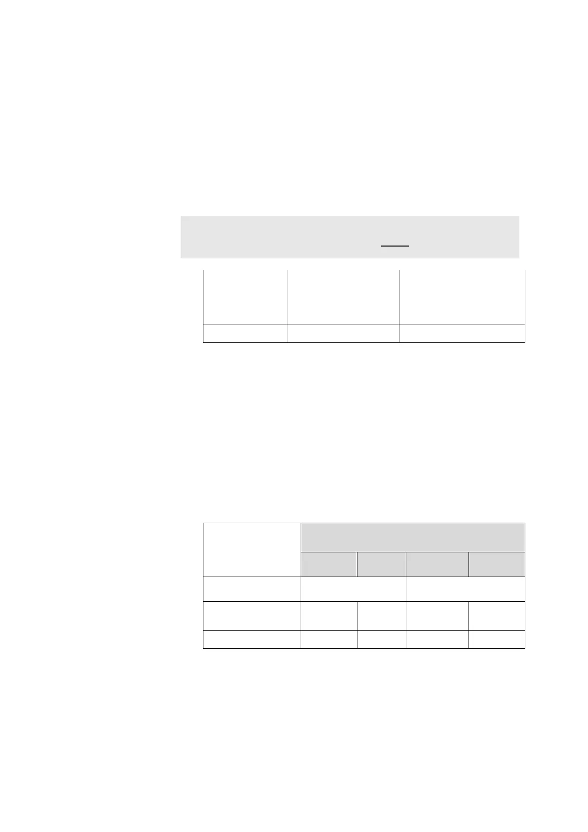
♦ <Active Signal>
This parameter switches an auxiliary voltage within the BINARY-IN
module either on or off.
Active signals from external current sources or open collector outputs
require no auxiliary voltage.
Non-active signals from external potential-free contacts require an
auxiliary voltage.
The selection whether you are dealing with active or non-active signals
can be changed at the instrument.
Note:
The setting of the parameter „Active Signal“ MUST
be identical for all three
channels of a BINARY-IN module.
Use of an active
signal
(auxiliary voltage off)
Use of an external
potential-free contact
(auxiliary voltage on)
Active Signal Yes No (Works pre-setting)
♦ <Active state>
This parameter defines the relationship between an electrical input
signal and the logical switch state.
The electrical input signal is either HIGH (nominal + 24 V) or LOW
(nominal 0 V). The parameter „Active state“ determines the respective
associated logical switch state, either ON resp. OFF. The active state is
always that state which is evaluated as ON.
The selection of the active state can be changed at the instrument using
the User Terminal.
The BINARY-IN module has three yellow LEDs to display the current
logical switch state of each of the three channels.
Current signal state
Electrical input signal
HIGH
(+24V)
LOW
(0 V)
HIGH
(+24 V)
LOW
(0 V)
Active state
high low
(Works default)
Logical switch
state
ON OFF OFF ON
LED state
ON OFF OFF ON