1 689 989 102 2019-05-24| Robert Bosch GmbH
Product description | FSA 050 | 25 en
4. Product description
4.1 Usage
FSA050 can either communicate via Bluetooth
with computer that has FSA7xx/500 software
(CompacSoft[plus]) installed or be used as a stand-
alone device.
The FSA 050 is designed for the performance of
insulation analysis on electric/hybrid vehicles. Voltage,
capacitance and resistance can also be measured.
4.2 Prerequisites for operation
withCompacSoft[plus]
Computer with operating system Windows7,
Windows8 or Windows10 and at least one vacant USB
interface for the Bluetooth USB adapter. The current
version of CompacSoft[plus] must be installed on the
computer.
i The FSA 050 has a Bluetooth transmission power
of 10 mW (Class 2) ex works. The Bluetooth class
can only be changed using the CompacSoft[plus]
software.
4.3 Scope of delivery
Designation Order number
FSA 050 –
Case 1 685 438 640
Measurement leads (red/black) with
terminals (red/black)
1 684 430 075
Bluetooth USB adapter –
Batteries (5x) –
Calibration certificate –
Remote sensor 1 684 430 074
CompacSoft [plus] DVD 1 687 370 275
Operating manuals 1 689 979 922
1 689 989 102
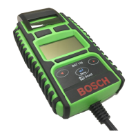
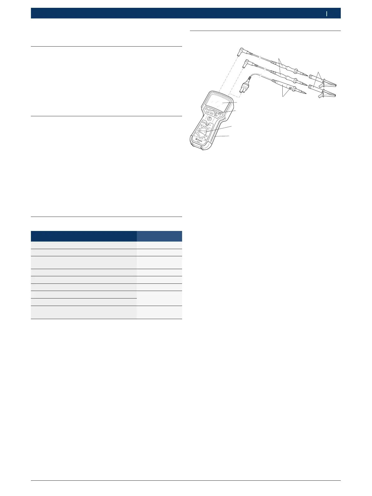
4.4 Description of device
TEST
STORE
DAR
A
PI
t
V
s
TRMS
458896-03_K
o
1
2
3
5
4
6
7
Fig. 1: FSA 050
1 Red/black measurement leads
2 Red/black terminals
3 Remote sensor with test/zeroing button (TEST)
4 LCD
5 Function keys
6 Rotary switch for measurement functions
7 Rubber cover
4.4.1 Remote sensor
The remote sensor can be used instead of the red
measurement lead. For insulation analysis, <TEST>
onthe remote sensor has the same function as <TEST>
on the FSA050.
The resistance of the black measurement lead and
the remote sensor can be zeroed for resistance
measurement (Ω).
Insulation analysis procedure with remote sensor:
1. Connect the black measurement lead to the black
negative socket of the FSA 050.
2. Connect the remote sensor to the 3-pin red
positive socket of the FSA050 (instead of the red
measurement lead).
3. Connect the black measurement lead and the
remote sensor to the circuit to be tested.
4. Select the correct range (50 V, 100 V, 250 V, 500 V
or1kV).
5. Press and hold <TEST> on the remote sensor.
Insulation analysis is performed.
6. To terminate insulation analysis, release <TEST> on
the remote sensor.
 Loading...