1 689 989 102 2019-05-24| Robert Bosch GmbH
26 | FSA 050 | Product descriptionen
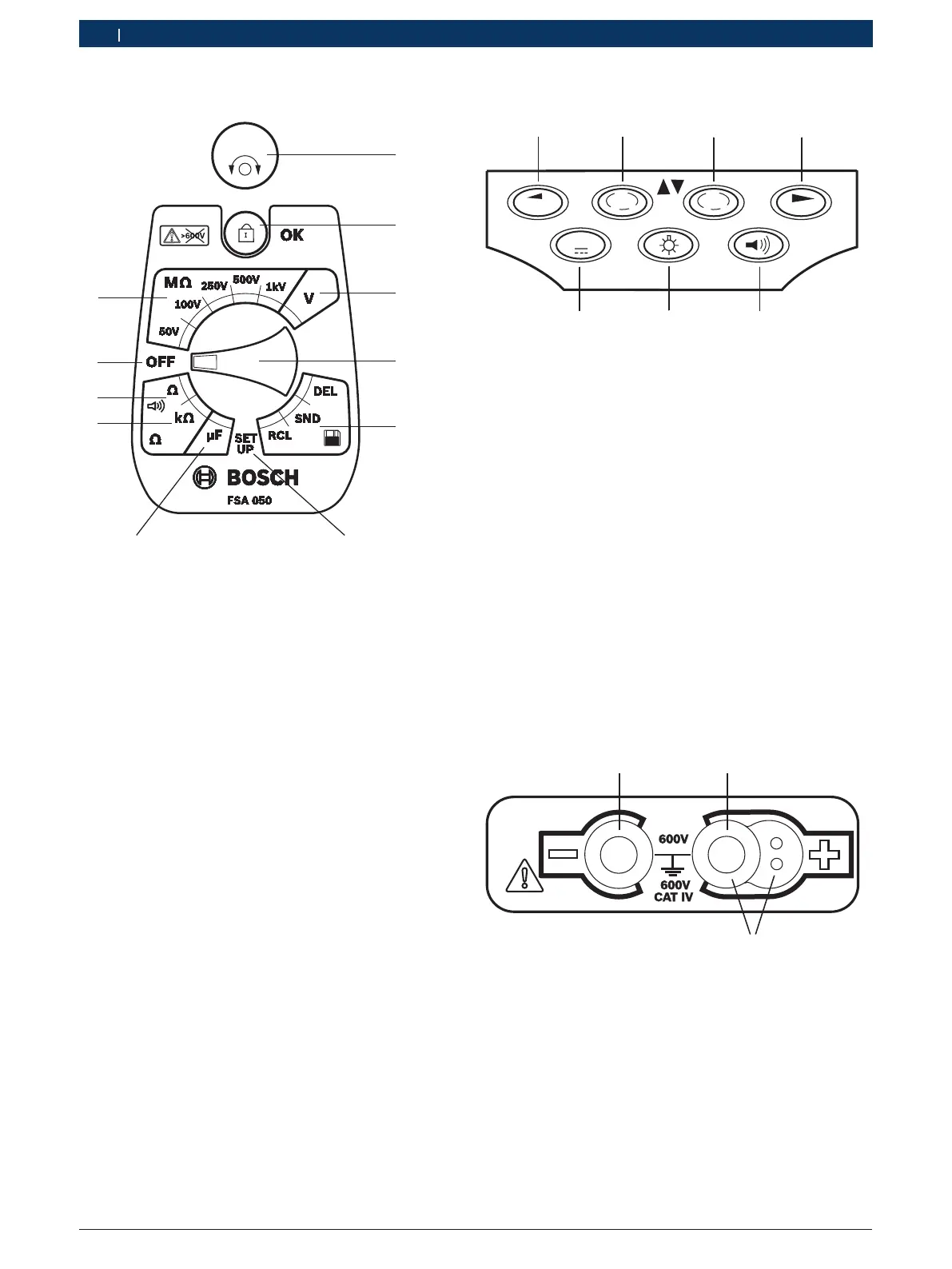
4.4.2 Rotary switch/buttons
459896-06_Ko
TEST
1
6
5
4
2
9
8
Fig. 2: Rotary switch/buttons
1 TEST (test/zeroing button)
2 /OK (lock/confirmation button)
3 Voltage measurement range
4 Rotary switch
5 Display(RCL)/Deletion(DEL) or data transfer(SND)
1)
of results
saved
6 SETUP menu
7 Capacitance measurement range
8 Resistance measurement range
9 Continuity measurement range
10 Off switch (OFF)
11 Insulation measurement ranges
1)
Data transfer only in conjunction with CompacSoft[plus]
software
4.4.3 Function keys
μA
V
DAR
STORE
TRMS
PI
t s
7
6
5
Fig. 3: FSA 050 function keys
1 STORE (save measurement result or selection key in
SETUPmenu)
2 DAR/PI/t or (insulation analysis or selection key for stored
measured values)
3 μA/s/V or (display of amps, seconds or volts or selection key
for stored measured values)
4 Continue (selection key in SETUP menu) or
Status display (FSA/STA) in the measuring ranges
5 Buzzer on/off
6 Background illumination on/off
7 TRMS or DC
LCD background illumination can be selected when the
FSA 050 is switched on (fig. 3, pos.6). The background
illumination goes out automatically after 20seconds.
The buzzer (fig. 3, pos. 5) can be activated for
continuity measurement. The symbol appears on the
LCD (fig.5, pos. 4).
4.4.4 Connection panel
3
Fig. 4: Connection panel
1 Connection socket (–) for black measurement lead
2 Connection socket (+) for red measurement lead
3 Sockets (+) for remote sensor
 Loading...