3-1
Bosch Security Systems 10/22 BLCC615I
SECTION 3
Wiring Diagrams
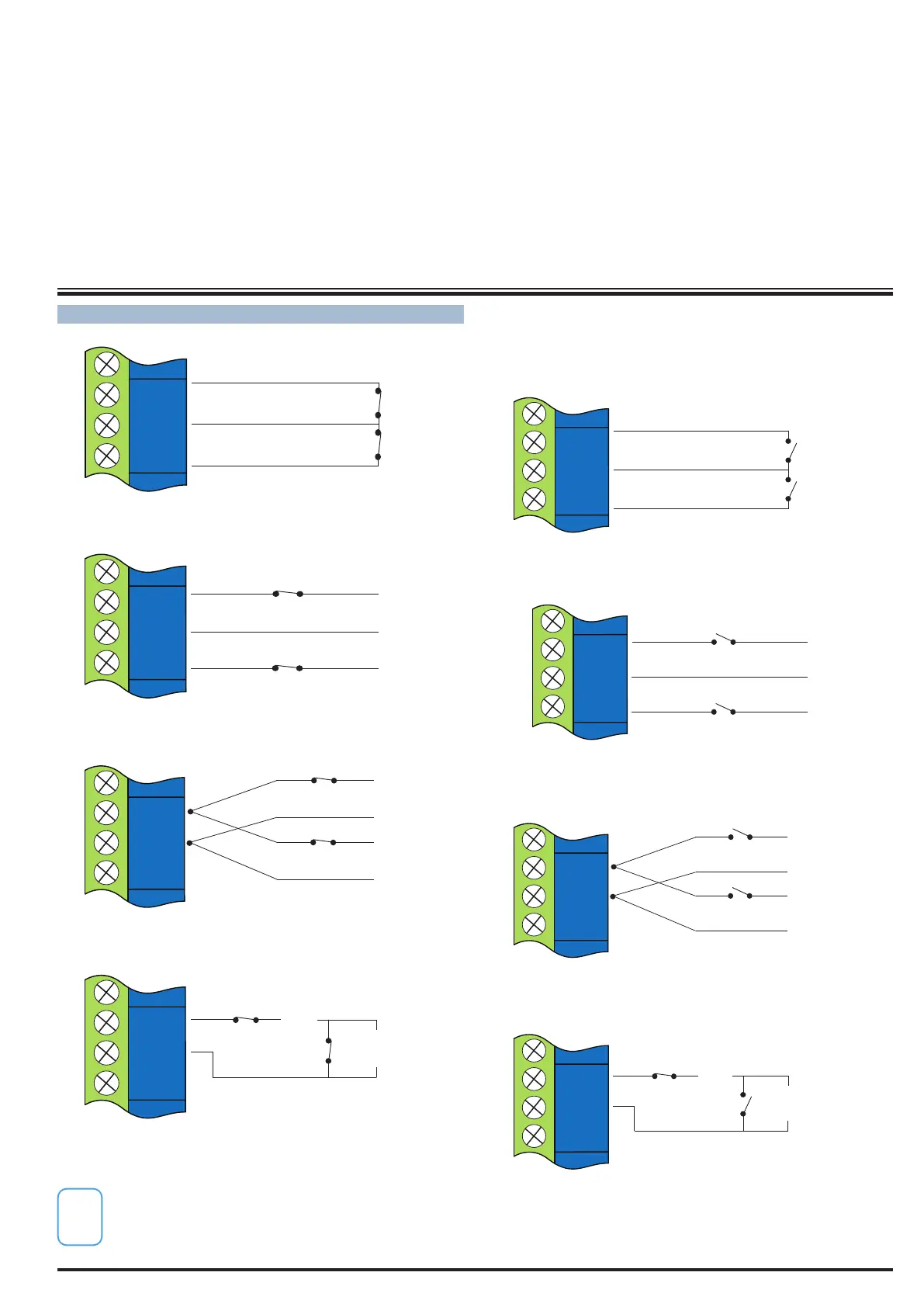
ZONE WIRING
N/C
N/C
ZONE 1
ZN 1
GND
ZN 2
Figure 13: N/C No EOL Zone
ZONE 1
N/C
N/C
ALARM
ALARM
ZN 1
GND
ZN 2
Figure 14: N/C Single EOL Zone
(3K3 EOL)
N/C
ALARM
ALARM
ZN 1
GND
ZN 2
ZONE 1
ZONE 9
Figure 15: N/C Split EOL Zone
1
2
TAMPER
(6K8 EOL)
TAMPER
N/C
N/C
ZN 1
GND
ZN 2
ALARM
ZONE 1
Figure 16: N/C Zone With Tamper
The Above diagrams display the zone wiring
configurations using Normally-Closed Alarm
contacts and Normally-Open Alarm Contacts. When
using Normally-Open Alarm Contacts you must
select Inverted Seal for each zone in MENU 3-1-8.
A shorted loop is a tamper condition for all EOL zone
configurations. .
2
ZONE 2
N/O
N/O
ZONE 1
ZN 1
GND
ZN 2
Figure 17: N/O No EOL Zone
ZONE 2
ZONE 1
N/O
N/O
ALARM
ALARM
ZN 1
GND
ZN 2
Figure 18: N/O Single EOL Zone
(6K8 EOL)
(3K3 EOL)
N/O
N/O
ALARM
ALARM
ZN 1
GND
ZN 2
ZONE 9
ZONE 1
Figure 19: N/O Split EOL Zone
TAMPER
(6K8 EOL)
TAMPER
(3K3 EOL)
N/C
N/O
ZN 1
GND
ZN 2
ALARM
ZONE 1
Figure 20: N/O Zone With Tamper