Solution 6000-IP
Installation Manual Programming Overview
4-4
Bosch Security Systems 10/22 BLCC615I
- = Outputs 05 to 08 and Outputs 11 to 16 are
Disabled or Not Available
DOOR ARRAY
This feature allows you to view door status in groups of 16.
From the installer programing mode press MENU 4-0-4 to
access the door array.
Press [OK] or [MENU] when finished.
The following information can be displayed depending
on the current door status.
L = Door Locked
U = Door Unlocked
O = Door Open
- = Disabled or Not Available
0000000001111111
1234567890123456
LLLLL---UUUUO---
Press OK or MENU
In the above example screen,
L = Doors 01 to 05 are Locked
O = Door 13 is Open
U = Doors 09 to 12 area Unlocked
- = Doors 06 to 08 and Doors 14 to 16 are Disabled or
Not Available
TESTING THE SYSTEM
You will need to be in programming mode before
accessing the test functions listed below.
Walk Test
Use the walk test command MENU 3-9-0 to test and verify
that all zones work correctly.
External Audible Test
Use MENU 4-9-0 to test and verify that all horn speakers
operate. This test will sound the horn speaker for two
seconds.
Internal Audible Test
Use MENU 4-9-1 to test and verify that all 12 VDC sirens
operate. This test will sound the siren for two seconds.
Strobe Test
Use MENU 4-9-2 to test and verify that the strobe operates.
This test will turn on the strobe until you manually stop
the test.
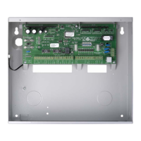
Battery Test
Use MENU 7-9-1 to test the back-up battery that is
connected to the control panel.
Communication Test
Use MENU 5-9-0 to test the reporting capability of the
control panel. You can also activate a communication test
by holding down the Test / Mail key on the keypad.
BASIC REPORTING REFERENCE
The following table is a shortform point ID listing.
For a complete listing of all the Contact ID and SIA event
reporting information that will be sent by the control
panel you will need to view the base station template
document that is included on the Solution Link CD or
contact your distributor.
Point ID Table Module Description
Ur999 Installer
Ur998 Remote User
Ur997 TimeZone
Ur996 Guard Tour
Ur001 - 995 Users
Ur000 Quick Arm
Zn001 - 264 Zones General
Zn001 - 064 Doors 1 - 64
Zn701 - 708 Door Controller 1 - 8
Zn711 - 718 Door Controller 9 - 16
Zn761 - 768 Lift Controller 1 - 8
Zn771 - 778 Lift Controller 9 - 16
Zn781 - 788 Input Expander 1 - 8
Zn791 - 798 Input Expander 9 - 16
Zn801 - 808 Universal Expander 1 - 8
Zn811 - 818 Universal Expander 9 - 16
Zn821 - 828 RF Receiver 1 - 8
Zn831 - 838 LAN Power Supply 1 - 8
Zn841 - 848 Serial Expander 1 - 8
Zn851 - 858 Output Expander 1 - 8
Zn860 GSM Module
Zn861 GSM Input 1
Zn862 GSM Input 2
Zn863 GSM Input 3
Zn864 GSM Input 4
Zn870 Ethernet Module
Zn871 Real Time Clock Module
Zn872 Voice Module
Zn873 Service Keypad
Zn881 - 888 Consoles 1 - 8
Zn891 - 898 Control Panel 1 - 8
Zn911 - 918 LAN Isolator 1 - 8
Zn921 - 928 LAN Isolator 9 - 16
Zn901 - 908 Destination Route 1 - 8
Zn971 - 978 Consoles 9 - 16
Zn901 - 908 Destination Route 1 - 8
Zn911 - 918 LAN Isolator 1 - 8
Zn921 - 928 LAN Isolator 9 - 16
Zn931 - 938 LAN Power Supply 9 - 16
Zn951 - 958 Output Expander 9 - 16