Solution 6000-IP
Installation Manual Installing the Hardware
2-4
Bosch Security Systems 10/22 BLCC615I
CABLE ENTRY (REAR)
MODULE
SPACE 1
MODULE
SPACE 3
MODULE
SPACE 2
MODULE
SPACE 5
MODULE
SPACE 4
MODULE
SPACE 7
MODULE
SPACE 6
CABLE ENTRY (REAR)
CABLE ENTRY (REAR)
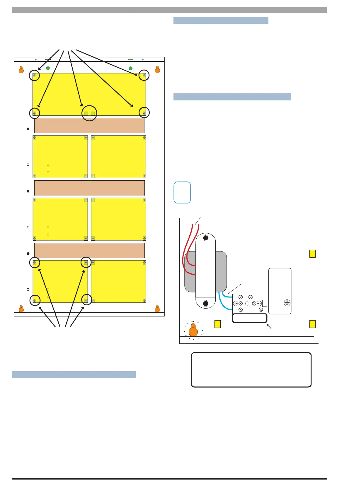
When installing small modules, you should
fit 4 mounting clips as shown.
When installing large modules you should fit 5
mounting clips as shown.
Clip 5 provides support under the main terminal
block only. No screw is fitted.
1
2
3
4
5
1
2
3
4
Figure 7: MW730 Configuration Examples
CONNECTING POWER TO THE PANEL
For normal operation, the panel requires both AC and DC
power sources. The AC source can be provided either
by an external adapter or by an internal transformer
depending on the model and country of sale.
When connecting using the AC adapter, feed the cable in
to the enclosure and terminate the wires on the removable
terminal block supplied before connection it to the PCB.
If using a 3 wire Adaptor, then the earth wire should also
be terminated onto the terminal block. Always check the
orientation of the terminal block with the PCB markings
before connecting it to the PCB.
CONNECTING THE BATTERY
The panel is supplied with a set of battey leads to suit
the chosen enclosure. Connect the Red Battery lead to
the Battery (+) terminal and the Black Battery lead to the
Battery (-) terminal on the PCB.
Once terminated onto the PCB connect the other end of
the leads to the battery paying attention to the polarity.
AC MAINS TRANSFORMER OPTION
On models with an internal transformer, a permanent
connection shall be made to the mains supply. See
Figure 8. This must be completed by a suitably qualified
electrician according to the applicable wiring standards
and regulations.
Next connect the transformer output wires (red) to the
removable terminal block supplied and then connect it
to the PCB. Always check the orientation of the terminal
block with the PCB markings before connecting.
For permanently connected equipment, a readily
accessable disconnect device shall be installed in a
location near to the equipment.
A
A
A A
TRANSFORMER
FUSE
220 - 240V A.C.
50-60Hz 150mA
8AG - 250V
250mA MAX
NEUTRAL
EARTH
ACTIVE
FUSED
L N
L
N
C
Transformer Output
(Red Wires)
Wiring must be carried out by
a licensed electrician following
applicable wiring standards
Transformer
Input
(Blue Wires)
A
= PCB Mounting Clip Holes
B
D
= Enclosure Mounting Holes
B
= Fused Terminal Block
C
= Transformer
D
Figure 8: Internal Transformer Connection Diagram