7-1
Bosch Security Systems 10/22 BLCC615I
SECTION 7
Input Programming
T
he control panel is capable of controlling up to 144
inputs in either hardwire and/or wireless configuration.
Each input can have its own unique name up to 20
characters to identify it on the system for display and
reporting purposes.
Under the commands menu you are able to view the
status of any input, bypass a zone, define which zones will
operate in chime mode, define which zones operate in
Part 2 mode and reset smoke detectors.
There is a command called 'Zone Array' that allows the
installer to view the condition of inputs in banks of 16.
This is extremely helpful when commissioning a system
or fault finding.
There are numerous configurations for each hardwire
input. The end of line resistor can be configured to
eliminate the need to change the end of line resistors on a
job when doing a change over. Input zones can be setup
as alarm only, alarm + tamper or even split end of line.
For normally open contacts the system is wired exactly
the same as for normally closed but there is an option
provided that inverts the sealed state of a zone.
When arming the system, all zones will be tested by default
and you may wish to turn this option off for certain zones
so that you don’t continually alert the operator during
arming.
The sensor watch feature lets you monitor zones to ensure
that they are working and detecting movement within a
determined programmable period.
Zones by default can be bypassed and you should disable
this option for zones you don’t want to be able to bypass,
for example 24hr, fire, holdup or panic zone types.
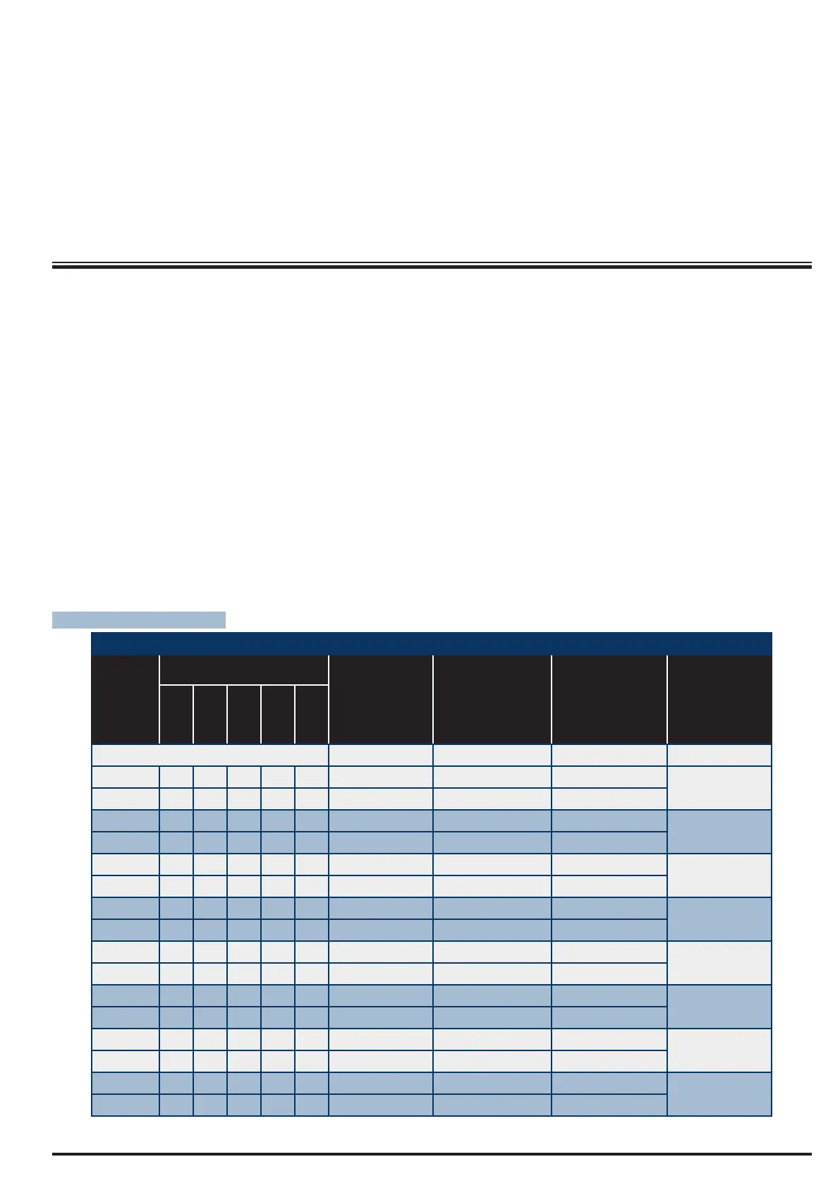
ZONE ASSIGNMENTS
Zone Assignment Table
Module
Number
Address Setting
Zone
Numbers
(Single EOL)
Zone
Numbers
(Alarm+Tamper
EOL)
Single or Alarm
+ Tamper EOL
With CM705B +
CM707B Module
Zone
Numbers
(Split EOL)
SW1 SW2 SW3 SW4 SW5
Control Panel 1 - 8 1 - 8 N/A 1 - 16
1 = OFF OFF OFF OFF OFF 17 to 24 17 to 24 17 to 24
17 to 32
25 to 32
2 = ON OFF OFF OFF OFF 33 to 40 33 to 40 33 to 40
33 to 48
41 to 48
3 = OFF ON OFF OFF OFF 49 to 56 49 to 56 49 to 56
49 to 64
57 to 64
4 = ON ON OFF OFF OFF 65 to 72 65 to 72 65 to 72
65 to 80
73 to 80
5 = OFF OFF ON OFF OFF 81 to 88 81 to 88 81 to 88
81 to 96
89 to 96
6 = ON OFF ON OFF OFF 97 to 104 97 to 104 97 to 104
97 to 112
105 to 112
7 = OFF ON ON OFF OFF 113 to 120 113 to 120 113 to 120
113 to 128
121 to 128
8 = ON ON ON OFF OFF 129 to 136 129 to 136 129 to 136
129 to 144
137 to 144
Table 17: Zones Assignments To Modules
 Loading...