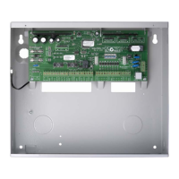
Solution 6000-IP
Installation Manual Output Programming
8-15
Bosch Security Systems 10/22 BLCC615I
Alarm Door Forced
This opion allows the control panel to sound an alarm
when a door forced events occurs It will also appear in
the keypad display as an alarm condition identifying the
door 'ALARM Door 1 Name'. To silence this alarm, you
must enter a valid PIN at the keypad.
Report DOTL
This option allows the control panel to report door open
too long and door open too long restore events. These
events follow the Access Route set in MENU 1-6-0.
Alarm On DOTL
This option allows the control panel to sound an alarm
when a door open too long event occurs.
Lift Door
This option allows users to unlock multiple doors they
have been assigned to at the same time using a token or
fingerprint.
A user presenting their fingerprint or token to a reader
that has both no door assignment (see MENU 6-1-7) and
badging required (see MENU 6-1-4) will unlock all doors
that has this option set.
Example
A user has been assigned to 16 doors. A LAN reader has
been assigned with no door assignment and also reader
badging enabled. Setting doors 09 to 16 with Option 8
- Lift Door, will allow the user to present their credentials
to unlock doors 09 to 16 at the same time.
If the same user presented their credentials at a reader
that has been assigned to a single door, only that single
door will unlock.
RF OUTPUTS
Solution 6000-IP control panels have the ability to add/
delete and test RF outputs when using Digiflex Smart
RF Receivers (PN: RF120 and/or RF121) via the following
menu’s.
MENU 4-3-0 Add RF Device
MENU 4-3-1 Delete RF Device
MENU 4-3-2 Test RF Device
Add RF Device
Outputs > RF Output
Add RF Device
MENU 4-3-0
This menu allows the installer to learn relay 1 and/or relay
2 of the RF160 module to operate an output configured at
the control panel.
1) Press [MENU] + [4] + [3] + [0] and use the up and
down arrows to highlight the output in the list,
then press [OK].
Op1 External Siren
Op2 Strobe Light
Op3 Smoke Sensor PWR
Press OK or MENU
2) The keypad will display the current RF160 ID.
Enter Device ID Op6
Garage Door
0000000000
Press OK or MENU
3) To learn the device RF ID, press and hold both relay
buttons on the RF160 module for 2 seconds or until
you see the RF and PGM indicators flash.
Enter Device ID Op6
Garage Door
0F9105130
Press OK or MENU
4) Press [OK] to save and continue or press [MENU] to
exit without saving.
Relay 1
Relay 2
Exit
Press OK or MENU
5) Select Relay 1 to use relay 1 or select Relay 2 to use
relay 2 of the RF160 module, then press [OK to save
and exit or press [MENU] to exit without saving.

 Loading...


