Solution 6000-IP
Installation Manual Wiring Diagrams
3-2
Bosch Security Systems 10/22 BLCC615I
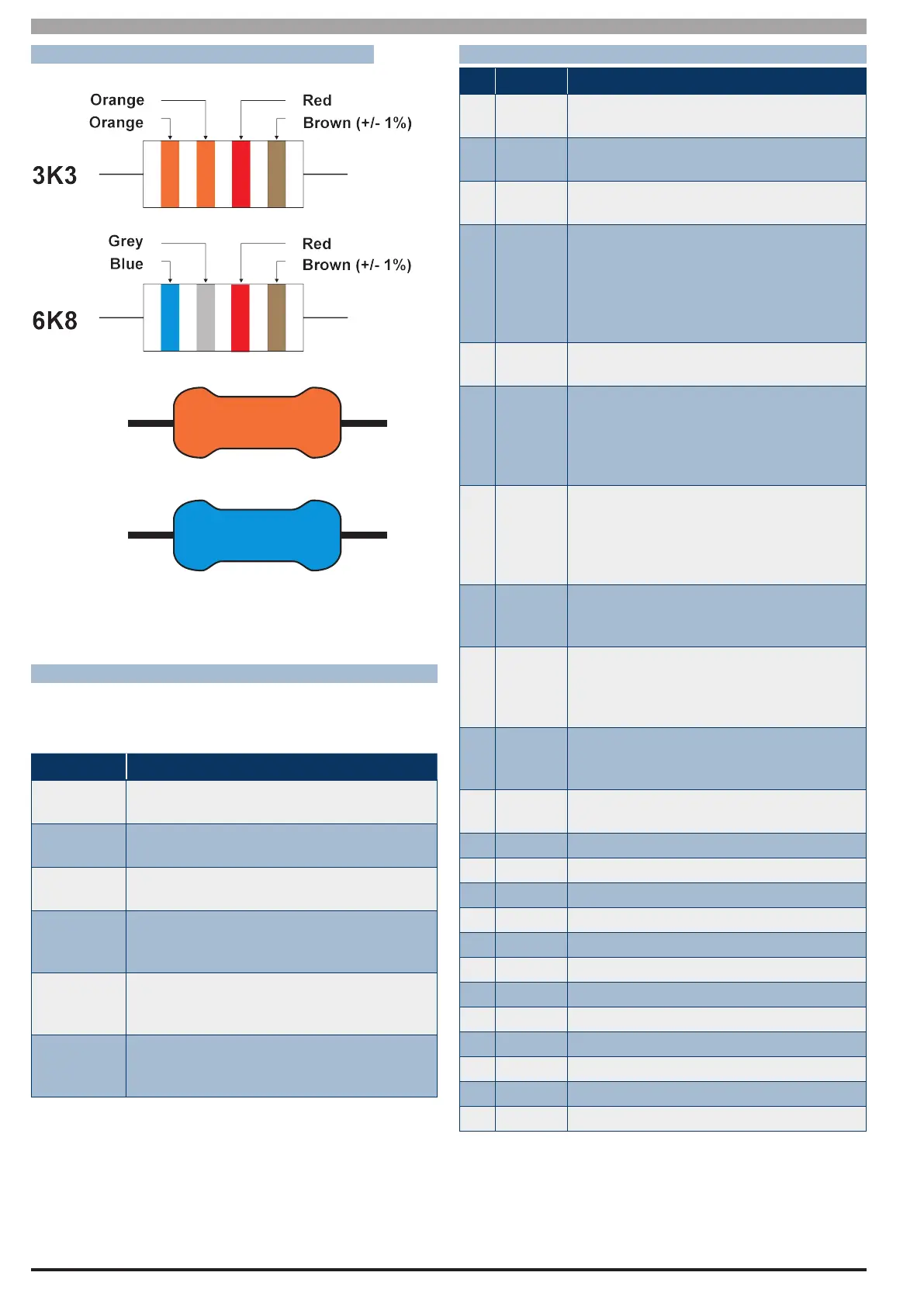
EOL RESISTOR COLOURS AND VALUES
Use either the 4 colour, or solid colour resistors supplied.
3K3 =
6K8 =
Orange
Blue
Figure 21: EOL Resistor Colour Chart
BOARD CONNECTORS
T
he following table lists the various sockets, pin headers
and switches located on the panel and their functions.
Connector
Description
Service
This socket allow you to connect a service Key-
pad to the panel during installation.
Tamper
This socket is used to connect the panel enclo-
sure tamper switch.
Default
This push button is used to reset the control
panel back to factory default.
Serial
This socket is used to connect serial devices
to the control system like the direct link pro-
gramming module.
Relay
The relay select PIN’s allow you to easily pro-
gram the relay common contact to switch ei-
ther +12v or GND by fitting a plug on link.
Expansion
Port
This port is used to connect additional mod-
ules to the control panel (eg. TCP/IP Interface
Module etc)
Table 10: Board Connector Descriptions
TERMINAL DESCRIPTIONS
Nº Name Description
1 Earth
Earth wire from this terminal is connected to
the Mains earth.
2
3
~ (AC)
~ (AC)
Connection of the AC plug pack transformer
4
5
BAT (-)
BAT (+)
Negative and positive connections to the
stand-by battery. 12 VDC / 7AH
6
7
8
9
10
11
+12 V
+12 V
+12 V
GND
GND
GND
These terminals are used to power detectors
and LAN devices up to 750 mA.
12
13
LAN +
LAN -
These terminals are used to power LAN
devices up to 750 mA.
14 LAN A
Connect the LAN A data terminal of any LAN
device (eg. Keypads, expansion boards) to
this terminal. The control panel supports up
to 300 m of 24/0.20 (18 AWG) wire on these
terminals.
15 LAN B
Connect the LAN B data terminal of any LAN
device (eg. Keypads, expansion boards) to
this terminal. The control panel supports up
to 300 m of 24/0.20 (18 AWG) wire on these
terminals.
16 COMM+
Alarm power capable of providing a
maximum of 2 Amp (+). This terminal is PTC
Fuse protected.
17
18
19
20
OUT 1
OUT 2
OUT 3
OUT 4
Programmable output, capable of providing
a maximum of 500 mA (-). This terminal is
PTC Fuse protected.
21
22
23
N/C
COM
N/O
2 A @ 24 VDC Relay Output - Form C contact
24 INPUT
Programmable Input for RF Receivers,
Keyswitch and other devices.
25 ZN 1 Zone 1 and 9 sensor loop input (+).
26 GND Common (-) for Zone 1 and 2 sensor loop.
27 ZN 2 Zone 2 and 10 sensor loop input (+).
28 ZN 3 Zone 3 and 11 sensor loop input (+).
29 GND Common (-) for Zone 3 and 4 sensor loop.
30 ZN 4 Zone 4 and 12 sensor loop input (+).
31 ZN 5 Zone 5 and 13 sensor loop input (+).
32 GND Common (-) for Zone 5 and 6 sensor loop.
33 ZN 6 Zone 6 and 14 sensor loop input (+).
34 ZN 7 Zone 7 and 15 sensor loop input (+).
35 GND Common (-) for Zone 7 and 8 sensor loop.
36 ZN 8 Zone 8 and 16 sensor loop input (+).
Table 11: Terminall Block Descriptions and Functions

 Loading...