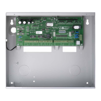
Solution 6000-IP
Installation Manual Programming Overview
4-3
Bosch Security Systems 10/22 BLCC615I
DEFAULTING THE SYSTEM
Defaulting the system will reset all programming options
back to the factory default setting. All programming
information will be erased.
Hardware Default
1) Remove all power to the system - AC and battery.
2) Press and hold the default push button, then apply
power to the control panel.
3) Release the default button, The panel will reset and
revert to normal operation when default is
complete.
Software Default
1) Enter programming mode.
[1][2][3][4] + [MENU]
2) Select factory default option.
MENU 7-0-4
3) The panel will reset and revert to normal operation
when the default is complete.
An optional CM255B Default Key may be purchased
to unlock both the Installer PIN and RAS Security
PIN. The default key is single use only. Refer to the
CM255B instructions for additional information.
You can disable factory defaulting using MENU 7-7-
4. If factory defaulting has been disabled you must
know the installer PIN to perform a factory default
otherwise the system will need to be returned to
your supplier for defaulting or you can purchase a
CM255B Default Unlock Key which will unlock the
panel in the field. Charges will apply for defaulting if
returned to the distrubutor.
TRIGGERING A DURESS ALARM
If your PIN is 2580, to send a duress report when the area is off,
Enter, [2][5][8][0] + [8][0] + [OK] or [ON].
If your PIN is 2580, to send a duress report when the area is on,
Enter, [2][5][8][0] + [8][0] + [OFF].
Duress alarms are triggered by entering the user PIN
followed by the last 2 digits of the user PIN followed
by the ON or OFF key.
DIRECT LINK PROGRAMMING
The panel can be programmed via the Solution Link™
Upload/Download software in either Direct Link or Remote
Link modes. For Direct Link you will need a CM910B Direct
Link/Flash module which is used to connect the panels
serial port to the PC.
Once the cable is connected you will need to hold down
the default switch on the panel for 5 seconds to initiate
the programming session. See the board layout drawings
in Section 3 of this manual for the default switch location.
ZONE ARRAY
The feature allows you to view the condition of all zones
on the panel in banks of 16 zones at a time. From the
installer programing mode press MENU 3-0-1 to access
the zone array.
Use the [] and [] arrow keys to scroll up and down the
zone banks and press [OK] or [MENU] when finished.
The following information can be displayed depending
on the current zone status.
N= NORMAL
S = SHORTED
A= ALARM
T= TAMPER
- = DISABLED
0000000001111111
1234567890123456
NSA-ANAT--------
Press OK or MENU
In the above example screen,
N = Zone 01 and 06 are Normal (Sealed)
S = Zone 02 is Shorted
A = Zone 03,05,07 are in Alarm (Unsealed)
T = Zone 08 is in Tamper Alarm (Unsealed)
- = Zone 04, 09-16 are Disabled (Unused)
OUTPUT ARRAY
This feature allows you to view output status in groups of
16. From the installer programing mode press MENU 4-0-
2 to access the output array.
Use the [] and [] arrow keys to scroll up and down the
output banks and press [OK] or [MENU] when finished.
The following information can be displayed depending
on the current zone status.
N = NORMAL - Off Condition
T = TRIGGERED - On Condition
F = FAULT - Overload Condition
- = DISABLED
1) Enter [MENU] + [4] + [0] + [2] and use the up and
down arrows to select the output group to view.
2) Use the up and down arrows at any time to move to
a new group. The keypad will display the following
output array information for outputs 1 to 16.
0000000001111111
1234567890123456
NNNNN---TF------
Press OK or MENU
In the above example screen,
N = Outputs 01 to 05 are Normal (Off)
F = Output 10 has a Fault (Overload)
T = Output 09 is Triggered (On)

 Loading...