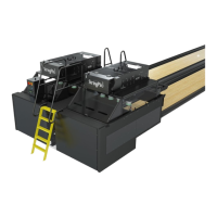
Section 3: Pinsetter Electronics 3-23
The following is a description of the functions of the StringPin High Voltage PCB:
Refer to Figures3-16,3-17,and3-18for fuse ratings and additional information.
(1) Pinsetter Motor Fuses (F1-F3, F11-F13) - Fuses used to protect the pinsetter’s string wagon
motor.
(2) Pinsetter Motor (J1,J3) - Output connections for the 3-phase power used for the pinsetter’s
string wagon motor.
(3) A/C Pinlight Fuses (F4-F5, F9-F10) - Fuses used to protect power to the optional multi-color
pinlight. The fuses are rated at 250V 2A 5 x 20 mm - Slow Blow.
(4) A/C Pinlight (J4-J7) - Output connections for power used for the optional multi-color pinlight.
(5) Ball Accelerator Fuses (F6-F8) - Fuses used to protect the ball accelerator motor.
(6) Ball Accelerator Motor (J2) - Output connection for the 3-phase power used for the accelerator
motor.
(7) Pinsetter Motor LED (D5, D11) - These LED light when the voltage is being sent to the
corresponding pinsetter’s string wagon motor.
(8) A/C Pinlight LED (D2, D4) - These LEDs lights when the voltage is sent to the optional multi-
color pinlight.
(9) Ball Accelerator LED (D3) - This LED lights when the voltage is being sent to the ball
accelerator motor.
(10) 24V Power LED (D14) - This LED lights when the 24VDC circuity is operating.
(11) Motor / Pinlight Control (J13) - Connection for the cable originating at the CPU. The High
Voltage board is “told” when to turn the motors and pinlights ON//OFF through this connection.
(12) D/C Pinlight LED (D7,D9,D11,D13) - These LEDs light to indicate when the voltage is being
sent to the D/C pinlight that is standard on the string pinsetter. LEDs D9 and D11 indicate
power is being sent to the corresponding pinsetter’s “white light” circuit, while LEDs D9 and
D13 indicate power is being sent to the corresponding pinsetter’s “blacklight” circuit.
(13) D/C Pinlight (J9-J12) - Output connections used to power the white/blacklight pinlights that
come standard on the Stringpin pinsetter. Connectors J9 and J10 connect to the “white light”
circuit of the pinlight and J11 and J12 connect to the “blacklight” circuit.
(14) D/C Pinlight Fuses (F14-F17) - Fuses used to protect the voltages going to the D/C pinlight.
The fuse is rated at 250V 1A 5 x 20 mm - Slow Blow. F14 and F16 protect the voltage going to
the “white light” circuits while F15 and F17 protect the voltage to the “blacklight” circuits.