Assembly
3
CLS Pro 600 – Line and Contrast Sensor 21/108
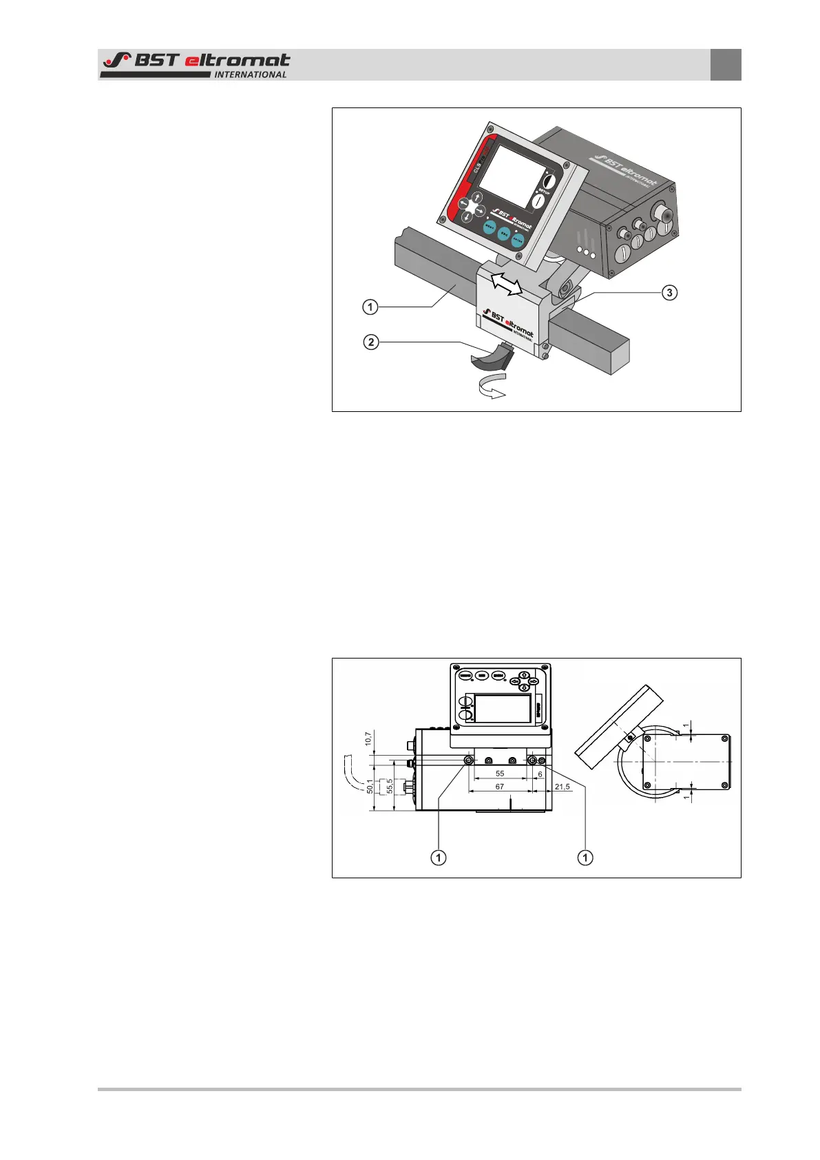
Fig.13: Sensor with supplied holder
①
Square Bar
②
Fastening Screw
③
Holder Unit
3.2.3 Installing the Sensor Using a Holder Supplied by the Customer
If the sensor has been supplied without a holder, then the cus-
tomer must provide a relevant securing device. Securing threads
are available at the sensor enclosure for this purpose. The connec-
tion sizes can be found in the following drawing.
Fig.14: Installing the Sensor Using a Holder Supplied by the Customer
①
M6 / 7 deep securing threads for securing holder provided
by customer (on both sides)

 Loading...
