2
Description
16/108 CLS Pro 600 – Line and Contrast Sensor
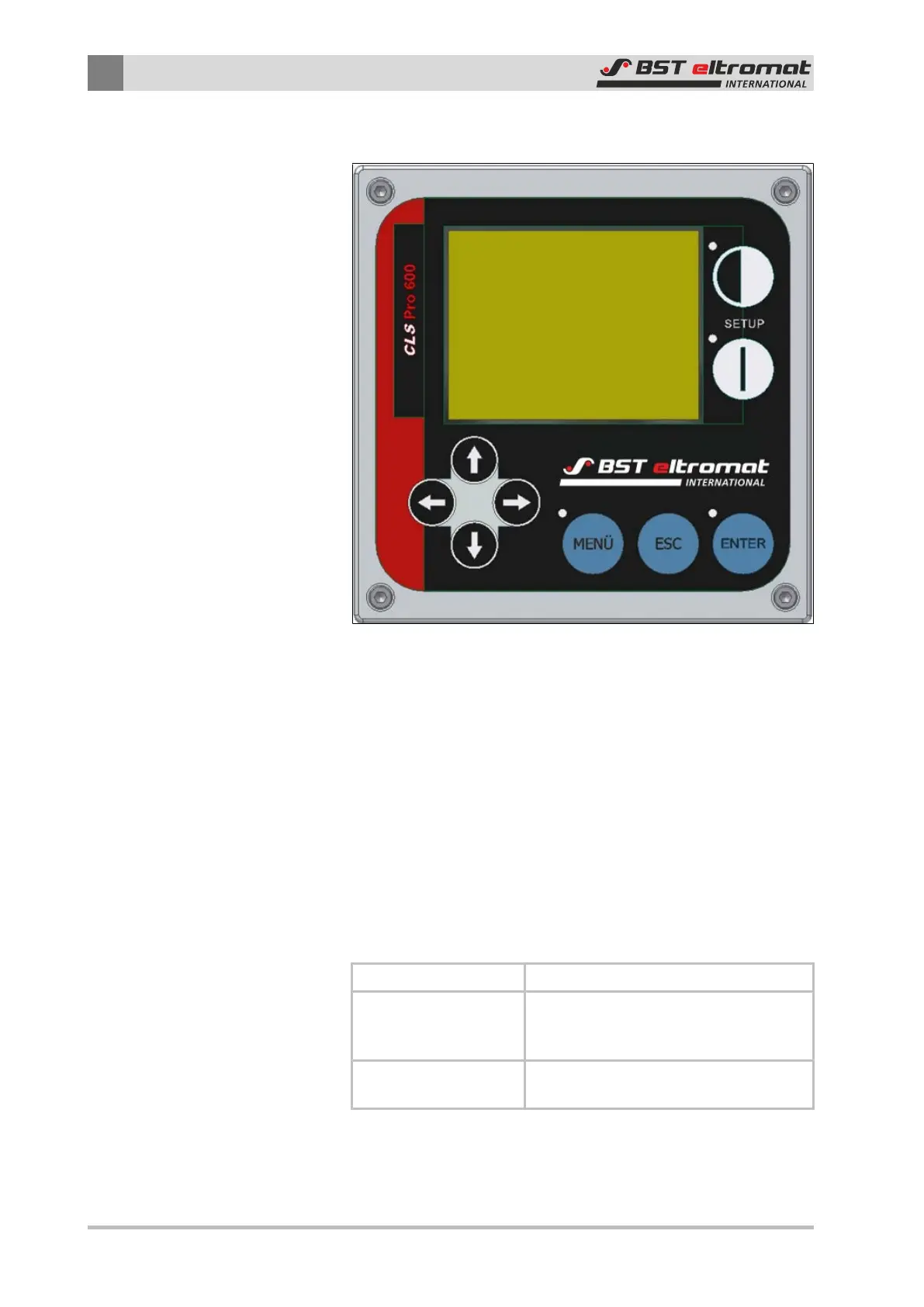
2.5 Control Panel
Fig.12: Control Panel
The control panel contains all of the display and operating con-
trols needed to operate the CLS Pro 600.
2.5.1 Graphic Display
Different parameters as well as main and quick menus (depending
on the mode selected) are displayed on the control panel’s screen
during operation.
The meaning of the individual symbols is described in chapter 6.2.
2.5.2 Control Panel
Three different groups of keys are integrated in the control panel
and they have the following functions:
SETUP Keys Used to select setup mode
Blue Keys:
Used to access the menu; import the
parameters or exit the parameter enter-
ing process
Arrow Keys:
Used to enter settings as shown in the
operating help page
You will find the separate key meanings listed in the table on the
following page.