3
Assembly
24/108 CLS Pro 600 – Line and Contrast Sensor
4. Take note of the cable guide for the connecting cable. Do not
crush or clamp the cable. There is a cut-out in the control
panel’s enclosure and the cable should be fed out through it.
5. Use the four securing screws to attach the control panel to the
sensor.
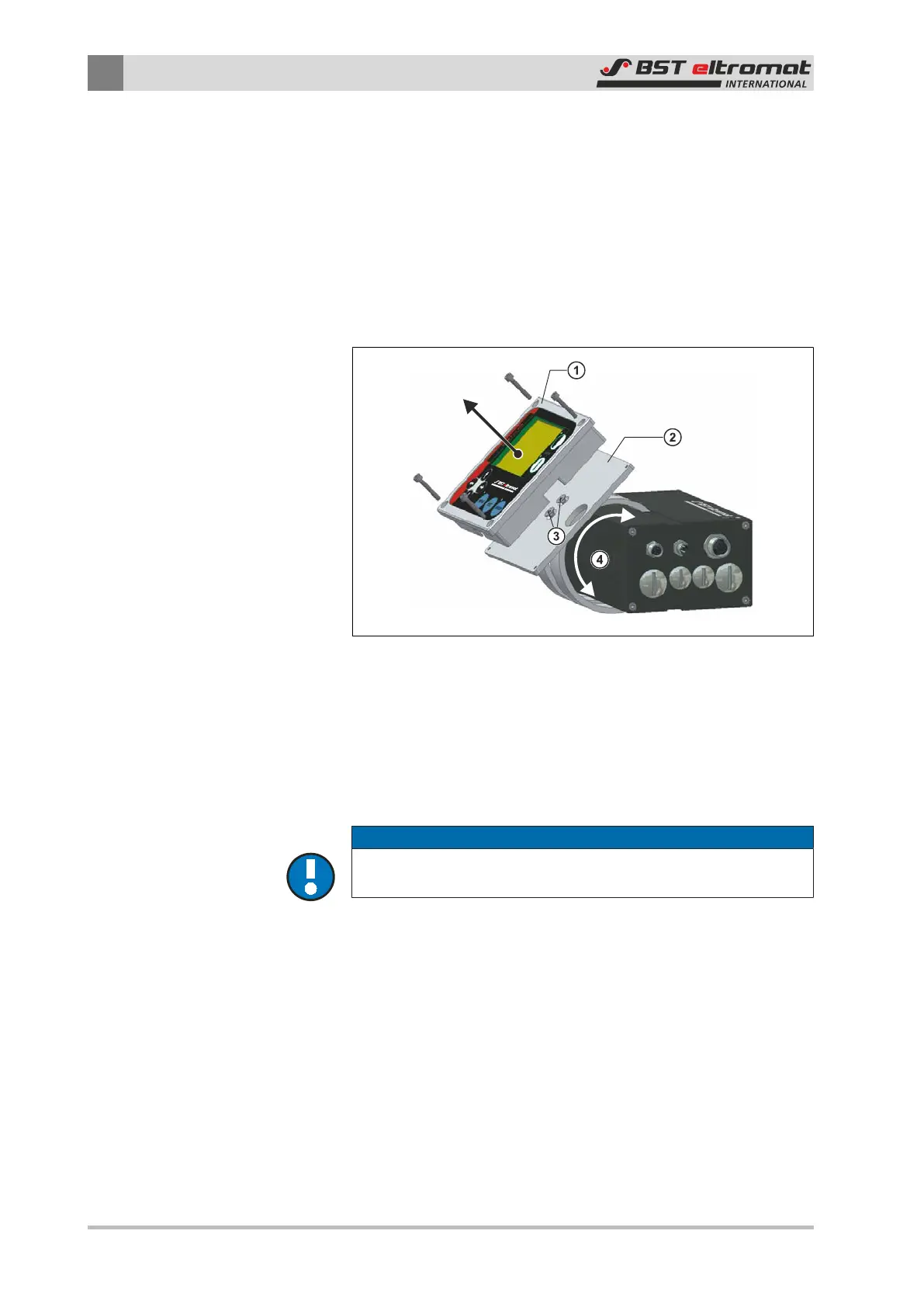
3.2.6 Rotating the Control Panel
The control panel can be rotated on the supporting ring (see
drawing in chapter 2.3.1).
Fig.19: Rotating the Control Panel
1. Therefore unscrew the control panel ① from the mounting
plate ② and remove it. After that loosen the fastening screws
of the mounting plate ③. Now rotate the mounting plate in
the desired direction ④.
2. Afterwards tighten the fastening screws ③ again and screw
the control panel ① onto the mounting plate ②.
NOTICE
Caution!
Don’t crush or clamp the connecting cable!