D
Appendix 4 - BST eltromat STB 1 Connections
104/108 CLS Pro 600 – Line and Contrast Sensor
D Appendix 4 - BST eltromat STB 1 Connections
General Information:
The sensor can be connected up to the customer’s controller us-
ing via a terminal strip (optional). A BST eltromat STB 1 must be
used in this case. This will link to the sensor via a cable and plug.
The separate cable wires will be fed to a terminal strip inside the
BST eltromat STB 1. The connections to the customer’s machine
can then be made from here.
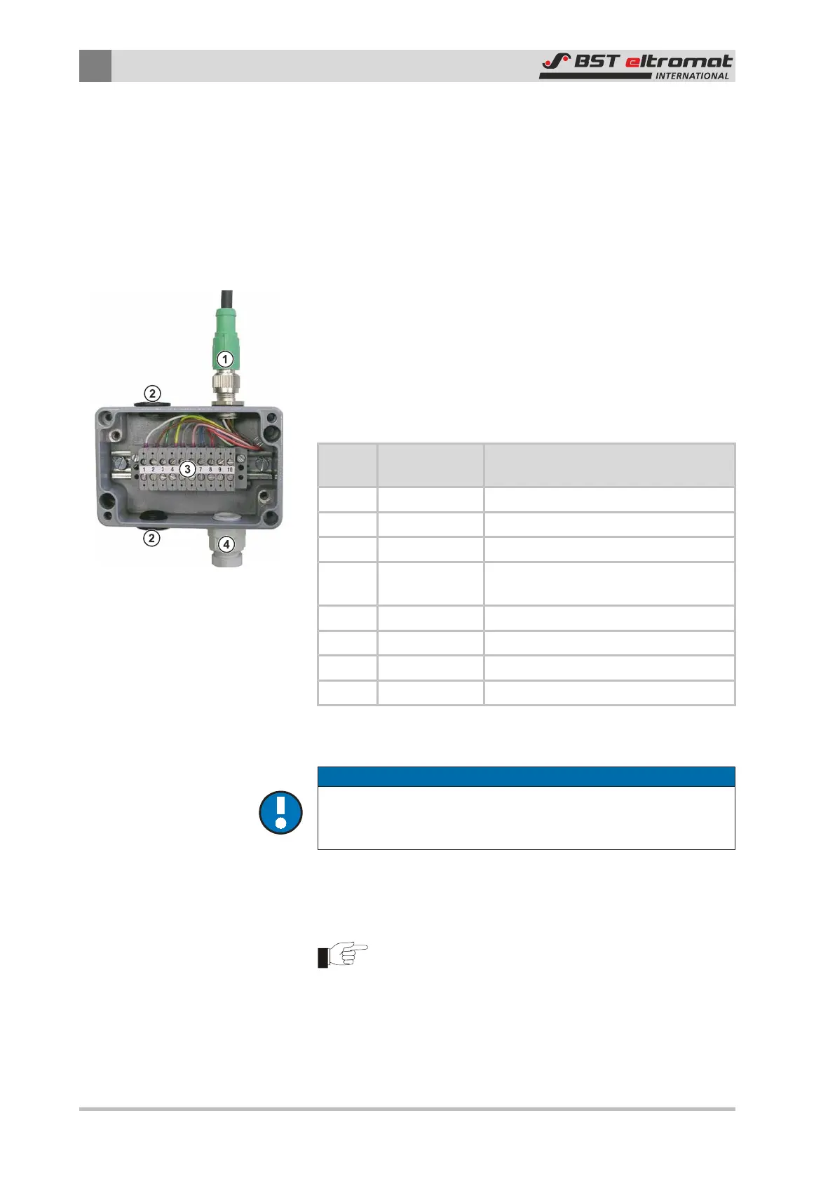
①
Connection Cable (from X80)
②
Optional Outputs (sealed by plugs)
③
Terminal Strip
④
M16 Cable Screws
Pin Assignment of the Terminal Strip:
Ter-
minal
Function Remark
1 GND Ground for Pin 2 and Pin 3
2 DOUT +24 V Output
3 LAMP_PLUS External lighting +24V output,
4 LAMP_TRIG
External lighting, trigger O/P, +12V / 5
mA
5 ANALOG_OUT Analog O/P 0 - 10 V
6 EXT_GND Insulated ground for Pin 7 and Pin 8
7 EXT_GEAR External Synchronization Cycle
8 EXT_RESET External Synchronization Reset
Installation:
NOTICE
Caution!
Only qualified and trained personnel are permitted to undertake
the electrical connections.
The system must be wired according to the accompanying con-
nection diagram or plugged into the appropriate cable sockets.
Note:
Standard wiring sleeves with collars (DIN 46228/Part 4)
must be used with all cable connections up to 0.75 mm².
Wiring sleeves must not be used with cables from 0.75
mm² up to a maximum of 1.5 mm².