Operation
6
CLS Pro 600 – Line and Contrast Sensor 47/108
6.2.2 Scanning Mode Display Window
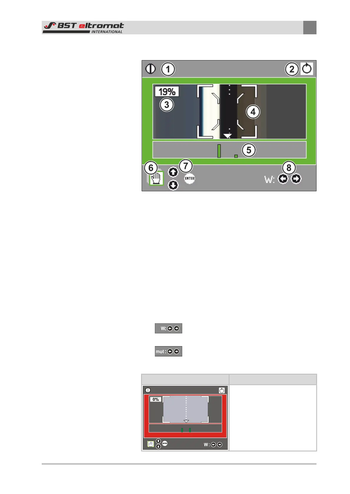
Fig.37: Scanning Mode Display Window
①
Status Bar: Shows you which modes the sensor and the con-
troller are working in. See Section 6.2.3 as well.
②
Current operating mode (controller)
③
Numerical contrast quality details
④
Measuring Area: Shows the tested edge / line and displays
the standard set point.
⑤
Contrast: Contrast quality of the tested edge / line is graph-
ically displayed.
⑥
Operating Help: Operating help has been integrated in the
footer. This shows you how the optimisation can be run in
the displayed window.
⑦
Pre-selects the ekrPro Com60 mode and other remote con-
trol functions
⑧
Set Point Adjustment (W)
in AUTO mode
Move guiding device left / right (mot)
in MAN mode
Background Colours Meaning
The background will flash red if
an error occurs (line or edge not
detected), regardless of the
mode being used.