7
Factory Default Settings
78/108 CLS Pro 600 – Line and Contrast Sensor
7 Factory Default Settings
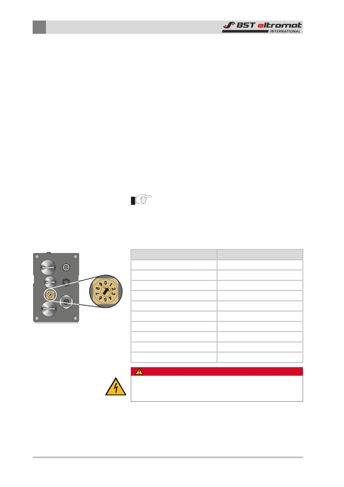
There are four stoppers fitted on the sensor’s connection side and
the relevant switches are located behind them. The control panel
switch is located on the back behind the stop. Which switches lie
behind which stoppers is described below.
7.1 Device Addresses
The device addresses for the sensor and the control panel are pre-
set in the factory. The settings usually do not have to be modified.
Check the device address settings if malfunctions or non-defined
sensor or operator panel processes occur or re-occur after the
devices have been changed.
7.1.1 Sensor Device Address
The sensor device address was preset to "1" in the factory (deliv-
ery state).
Caution!
You are only allowed to modify the device address if au-
thorized to do so by the manufacturer!
The sensor’s device address is set up using the S1 rotary switch.
The current setting is displayed in the System info sub-menu as
Sensor Node (see Section 6.7.5).
Switch Position Address
0 reserved
1 41
2 42
3 43
4 44
5 45
6 46
7 47
8 48
9 reserved
DANGER
Danger from the power supplies!
You are only allowed to open the sensor if the power supply has
been switched off!
Setting the Device Address:
1. Switch-off the power to the sensor.
2. Unscrew the stopper in the sensor enclosure