Description
2
CLS Pro 600 – Line and Contrast Sensor 13/108
③
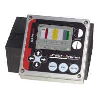
Display Area
The content shown in this area depends on the mode set-
ting. Detailed descriptions can be found in Section 6.2.1 for
the setup mode and in Section 6.2.2 for the scanning mode.
2.4.2 Set Position
The set position is the required line / contrast transfer point posi-
tion in the sensor scanning area. It can be set up in Automatic
mode using the control panel’s arrow keys (see Chapter 6.3.2).
The set point position will be indicated by a white triangledis-
played on the control panel’s screen.
Fig.8: SET POINT Position without deviation
①
Center of Measuring Range
②
Contrast Quality (graphical)
③
Standard SET Position
The deviation will be faded in as plaintext during displacement of
the set position. The deviation can take positive values and negat-
ive values as well.

 Loading...