2
Description
10/108 CLS Pro 600 – Line and Contrast Sensor
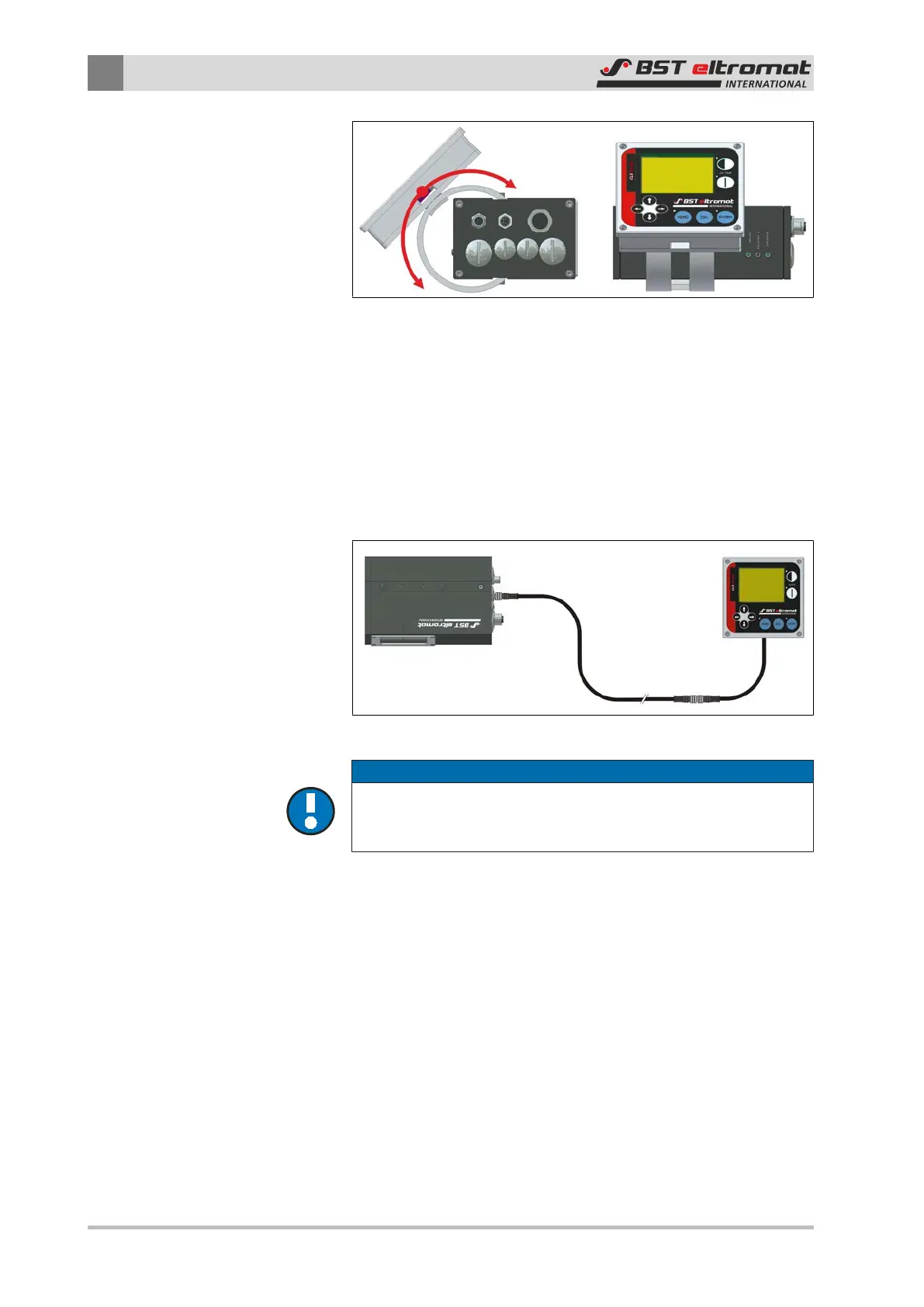
Fig.1: Sensor with fitted control panel
Sensor with Removable Control Panel
If necessary (i.e. if the sensor is installed in a difficult to access po-
sition on the machine) the control panel can be removed and in-
stalled in a central control console or a customer-supplied control
station. In this case the connection between the sensor and con-
trol panel is completed using a cable extension that is available as
an optional extra.
Sensor
Control Panel
Cable Extension
(2 m, 5 m, 10 m)
Fig.2: Sensor with control panel removed
NOTICE
Please note:
The length of the connection cable between the sensor and the
control panel must never exceed 20 m (maximum).
2.3.2 Functional Principle
The sensor records the actual position of a line or a contrast trans-
ition point on the material web in automatic mode and then trans-
mits the relevant information to the interconnected controller.
The controller compares the actual recorded position against the
default set point position. A relevant correction signal will be sent
to the guiding device’s actuator if a deviation is found to exists
between the two values. The actuator will drive the guiding device
(rotating frame or swivelling roller guide) until the material web
returns to its set point position.
The CLS Pro 600 sensor can be used in the following configura-
tions: