Factory Default Settings
7
CLS Pro 600 – Line and Contrast Sensor 79/108
3. Check the S1 rotary switch setting The S1 rotary switch must be
set to position 1.
4. Switch the S1 rotary switch to position 1 if necessary.
5. Screw the stopper back into the sensor enclosure.
6. Switch on the mains voltage.
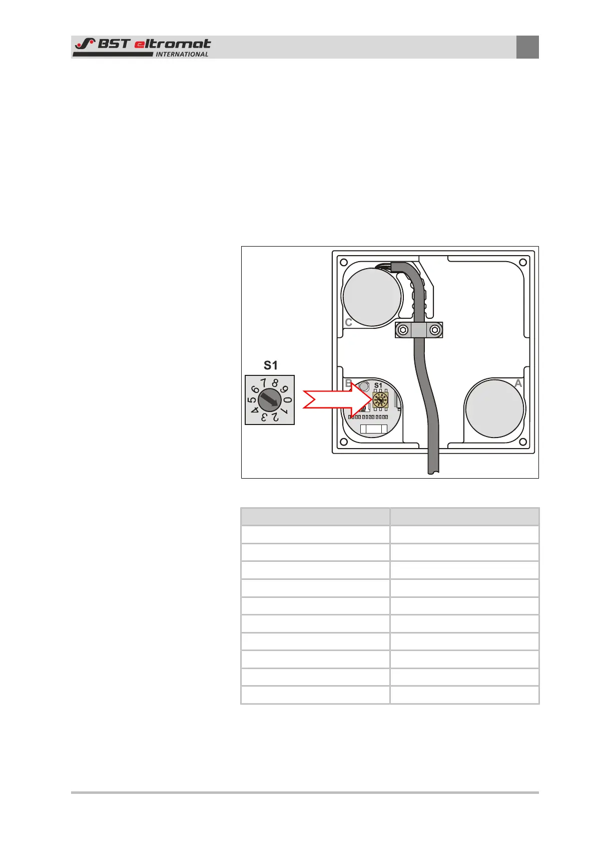
7.1.2 Control Panel Device Address
The control panel’s device address is set up using the S1 rotary
switch fitted on the panel board. The S1 rotary switch is mounted
behind stopper B on the back of the control panel.
Fig.41: Setting the devicev address
Switch Position Address
0 reserved
1 111
2 112
3 113
4 114
5 115
6 116
7 117
8 118
9 reserved
The control panel’s device address was preset to 1 in the factory
(delivery state). The current setting is displayed in the System info
sub-menu as Commander Node (see Section 6.7.5).