9
Technical Data
88/108 CLS Pro 600 – Line and Contrast Sensor
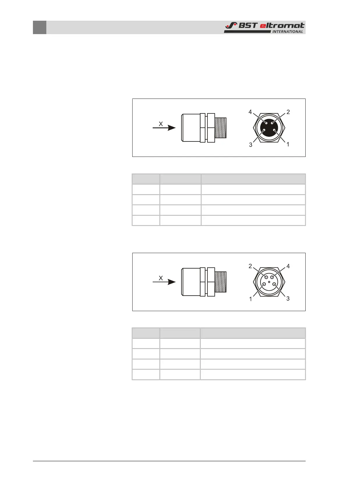
9.2.6 Plug Assignment
A 4-pin micro style M8 connector is used to connect the control
panel to the sensor and the sensor to the controller.
Plug X100 - Control Panel:
Fig.48: Contact assignment of the X100 plug connector
Contact Signal Remark
1 +24V +24 V Power Supply
2 CAN_H CAN-Bus
3 GND Power Supply Ground
4 CAN_L CAN-Bus
Plug X101 - Controller Connection:
Fig.49: Contact assignment of the X101 plug connector
Contact Signal Remark
1 +24V +24 V Power Supply
2 CAN_H CAN-Bus
3 GND Power Supply Ground
4 CAN_L CAN-Bus