Assembly
3
CLS Pro 600 – Line and Contrast Sensor 27/108
3.3.3 Wall Mounting
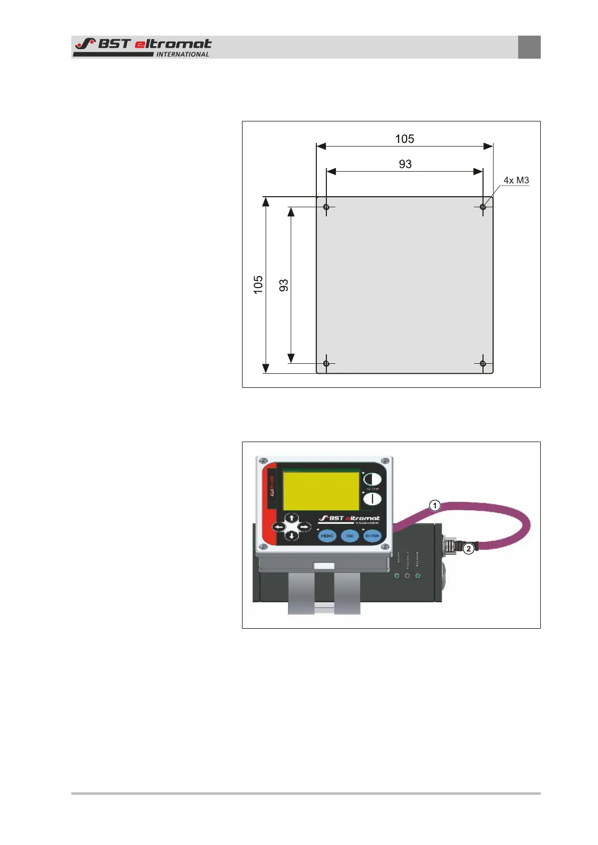
Securing Hole Diagram
Fig.21: Control Panel Enclosure
Preparations:
Fig.22: Unplug the connecting cable
①
Control Panel Connecting Cable
②
Plug X100
1. Unplug the plug ② of the control panel connecting cable ①
from the sensor (plug X100).